Online forecasting method of continuously cast bloom real-time temperature field based on infrared thermal imaging

A technology of infrared thermal imaging and infrared thermal imager, which is applied in the direction of casting equipment, indicating equipment/measuring equipment configuration, manufacturing tools, etc., can solve the problem of inability to guarantee spatial continuity, low accuracy of temperature measurement data, and inability to truly reflect Issues such as the internal temperature of the slab

Inactive Publication Date: 2010-03-10
NORTHEASTERN UNIV
View PDF1 Cites 22 Cited by
  • Summary
  • Abstract
  • Description
  • Claims
  • Application Information

AI Technical Summary

Problems solved by technology

Patent CN1410189A provides a method for measuring the surface temperature of a slab based on a pyrometer, which can only provide a single-point measurement result of the surface temperature; patent CN1844409A proposes a temperature field based on an infrared image, but this method only involves blast furnace metallurgy The furnace throat temperature field of the process can only display the external surface temperature of the charge; the patent CN2188439Y provides an online measurement device for the internal temperature of the continuous casting slab, but this measurement method can only be used when the casting is nearing the end, and is subject to the casting tail. The influence of slab overcooling cannot truly reflect the internal temperature of the slab; the master’s degree thesis of Chongqing University in July 2008 (the influence of water mist m

Method used


Image

  • Online forecasting method of continuously cast bloom real-time temperature field based on infrared thermal imaging
  • Online forecasting method of continuously cast bloom real-time temperature field based on infrared thermal imaging
  • Online forecasting method of continuously cast bloom real-time temperature field based on infrared thermal imaging

Examples


Embodiment Construction

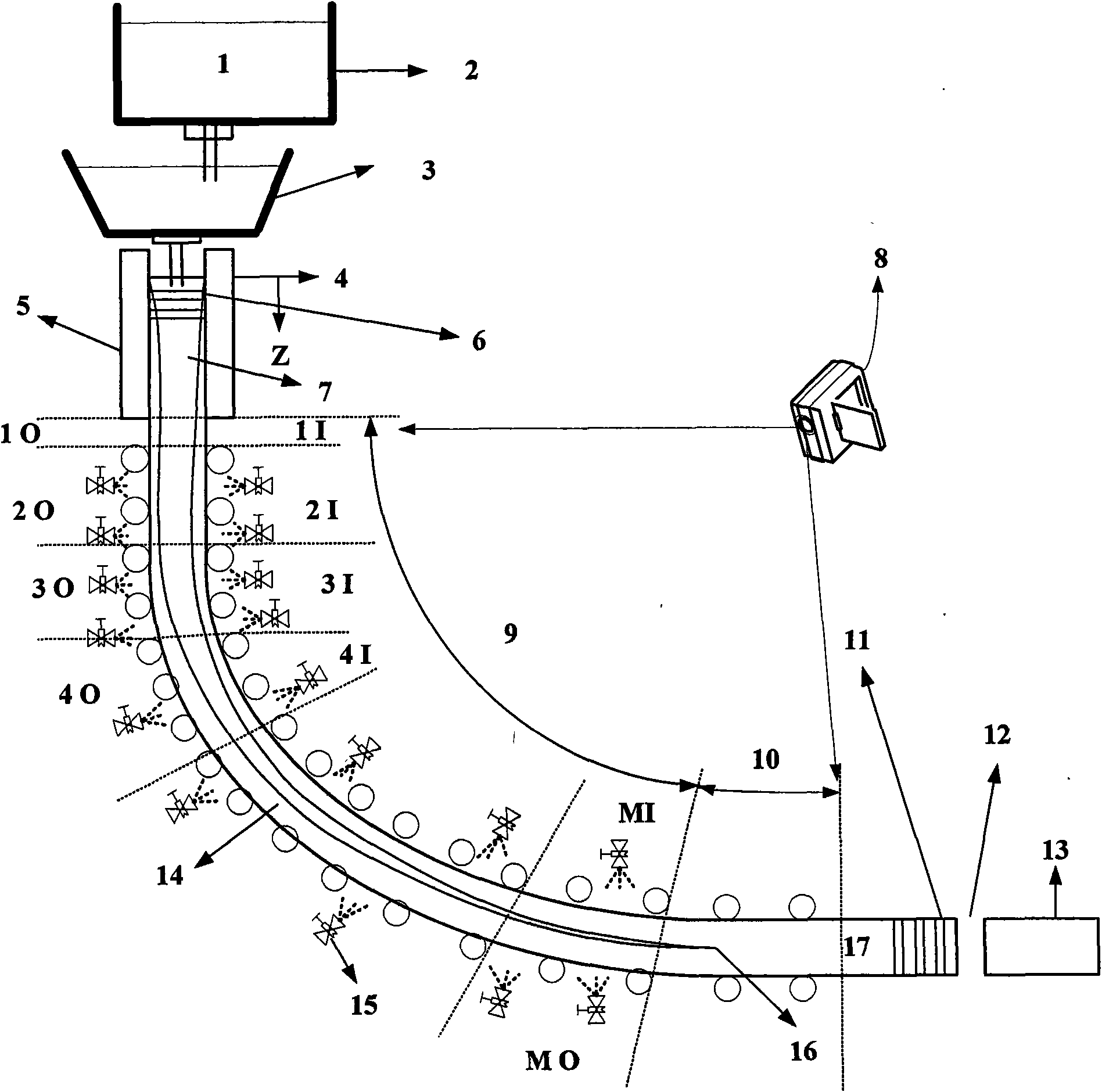
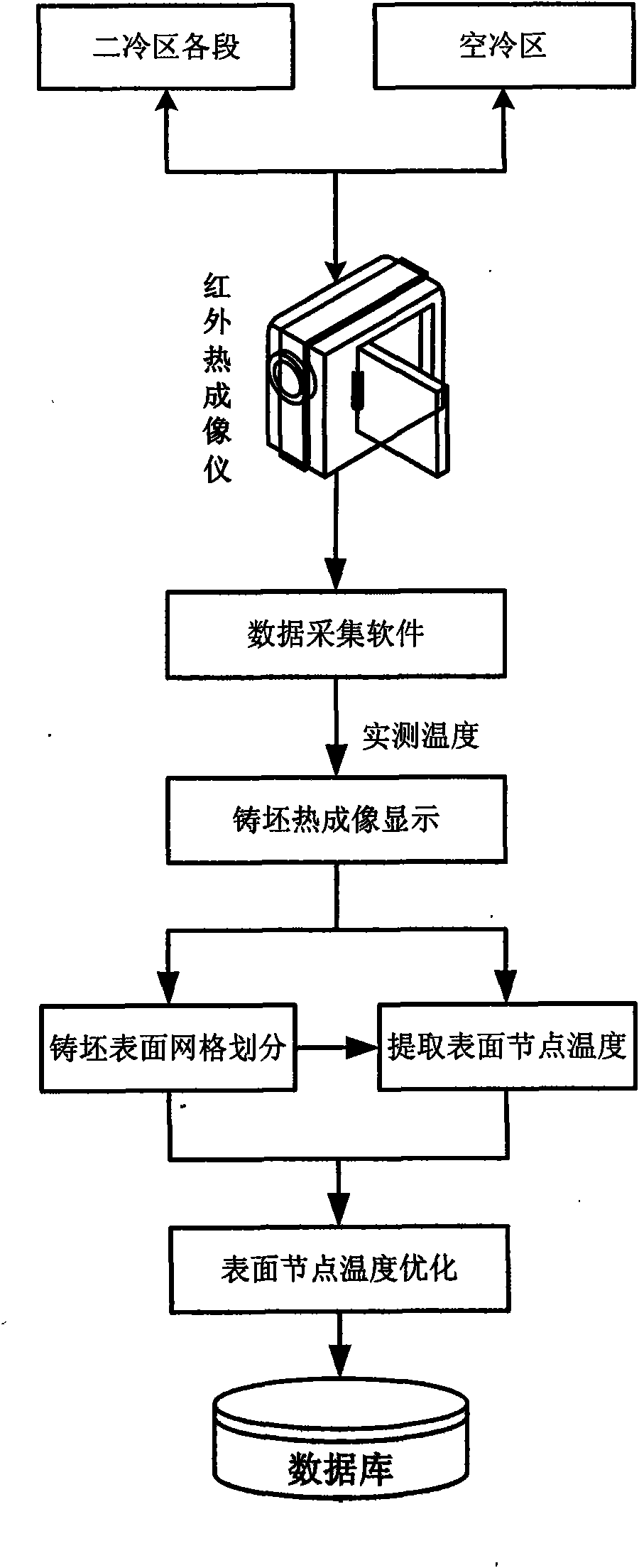
[0055] The present invention will be further described in conjunction with accompanying drawing: figure 1 It is a schematic diagram of continuous casting process and thermal imaging temperature measurement. The molten steel 1 in the ladle 2 enters the crystallizer 5 through the tundish 3, and the first tracking unit 6 is formed at the meniscus 4 of the mold 5, and the first tracking unit 6 enters the secondary cooling section 9 along the liquid direction hole 7, and the second Both the inner arc I and the outer arc O of the cold section 9 are provided with aerosol nozzles 15, the tracking unit enters the air cooling section 10, the strand 17 solidifies at the solidification end point 16, and the infrared thermal imager 8 collects the temperature of the secondary cooling section 9 and the air cooling section 10. Thermal image, the last tracking unit 11 cuts at the cutting point 12 to form a strand 13 .

[0056] Install the infrared thermal imager in the secondary cooling zone and


PUM


Abstract

The invention provides an online forecasting method of a continuously cast bloom real-time temperature field based on infrared thermal imaging, relating to monitoring and analysis of surface temperature of a billet. The invention provides an online checking method for determining heat transfer coefficients in a secondary cooling zone and an air cooling zone to check the heat transfer coefficientsin the secondary cooling zone and the air cooling zone in real time; compared with the prior art, the method improves precision of forecasting the real time temperature field through sectional checking method of heat transfer coefficients, more precisely forecasts temperature field on the surface and at the interior of the casting blank and precisely reflects the solidification process of the casting blank; therefore, the method provides necessary data support for the precise and effective implementation of the casting technology of secondary cooling dynamical water distribution, solidification end electromagnetic agitation and solidification end dynamic pressure, and the like.

Description


Claims


Application Information

Patent Timeline
Owner NORTHEASTERN UNIV
Why Eureka
Try Eureka