Monitoring method of color sequence monitor
A display method and display technology, which can be applied to static indicators, instruments, identification devices, etc., can solve the problems of color mixing in the display screen, and achieve the effect of improving the color mixing phenomenon.
- Summary
- Abstract
- Description
- Claims
- Application Information
AI Technical Summary
Problems solved by technology
Method used
Image

Examples
no. 1 example
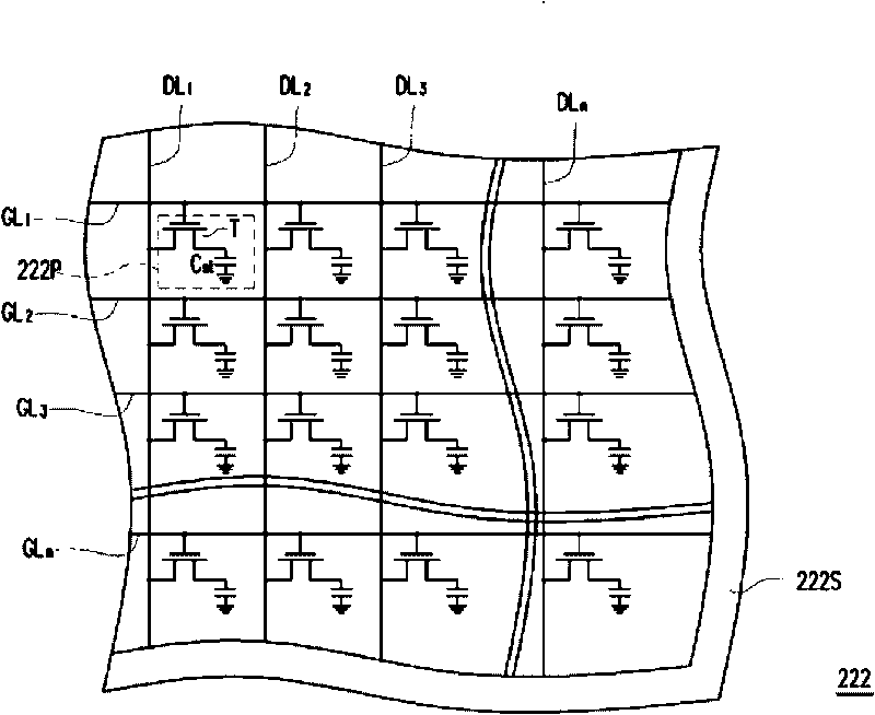
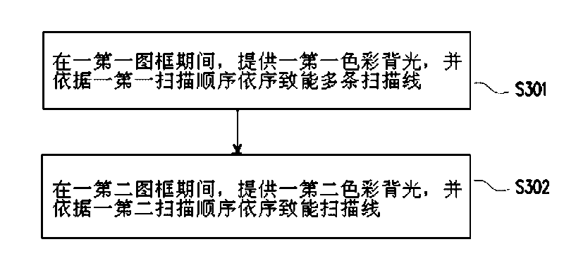
[0048] image 3 A flowchart illustrating a display method of a color sequential display according to an embodiment of the present invention, and Figure 4 A driving waveform diagram of a color sequential display according to an embodiment of the present invention is shown. Please also refer to figure 2 , image 3 as well as Figure 4 , SG 1 、SG 2 、SG 3 、SG i-1 with SG i For example, respectively represent the scan line GL 1 The scanning signal waveform on the scanning line GL 2 The scanning signal waveform on the scanning line GL 3 The scanning signal waveform on , the scanning signal waveform on the (i-1)th scanning line (not shown), and the scanning signal waveform on the i-th scanning line (not shown), and i is a positive integer.
[0049] First, in step S301, during a first frame period T1, the embodiment enables the scanning lines GL sequentially 1 、GL 2 、GL 3 ,...,GL n , that is, the time point of enabling the (i-1)th scan line is earlier than the time point
no. 2 example
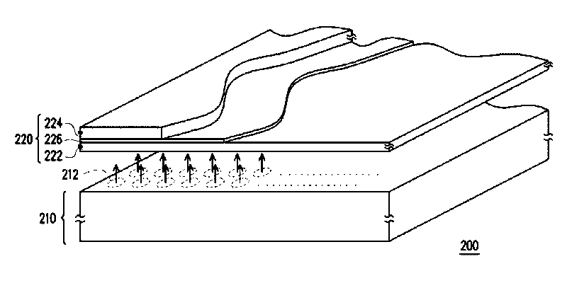
[0060] about figure 1The display method of the color sequential display 200 shown can also be described as follows. The spirit of this embodiment is similar to that of the first embodiment, and the main difference between this embodiment and the first embodiment is that: the backlight module 210 in the color sequential display 200 of this embodiment further provides a fourth color backlight.
[0061] Please also refer to the following figure 1 as well as figure 2 , in this embodiment, the scanning line GL is enabled during the first frame period to the fourth frame period 1 、GL 2 、GL 3 ,...,GL n The actions can refer to the description of the first embodiment, wherein the first color backlight (such as red backlight), the second color backlight (such as green backlight) and a third color backlight (such as blue backlight). However, during the fourth frame period, this embodiment provides, for example, a fourth color backlight that can emit white light. In practice, the w
no. 3 example
[0064] about figure 1 The display method of the color sequential display 200 shown can also be described as follows. The spirit to be described in this embodiment is similar to that of the first embodiment, and the main difference between this embodiment and the first embodiment is that each frame period in this embodiment further includes a plurality of sub-frame periods, wherein the same frame The backlight provided in different sub-frame periods in the period has different colors.
[0065] Please also refer to the following figure 1 as well as figure 2 , in this embodiment, the scanning line GL is enabled during the first frame period and the second frame period 1 、GL 2 、GL 3 ,...,GL n For the actions, reference may be made to the description of the first embodiment, and no further description is given here. However, in this embodiment, the first frame period is further divided into a first sub-frame period, a second sub-frame period and a third sub-frame period, and t
PUM
 Abstract
Description
Claims
Application Information
 - R&D Engineer
- R&D Manager
- IP Professional
- Industry Leading Data Capabilities
- Powerful AI technology
- Patent DNA Extraction
Browse by: Latest US Patents, China's latest patents, Technical Efficacy Thesaurus, Application Domain, Technology Topic.
© 2024 PatSnap. All rights reserved.Legal|Privacy policy|Modern Slavery Act Transparency Statement|Sitemap