High-speed pulse isolation and transmission circuit

A high-speed pulse and transmission circuit technology, which is applied in the electrical isolation of high-speed pulse signals in industrial sites, circuits, and high-speed pulse isolation circuits, can solve problems such as large volume, short life of relay contacts, and poor anti-electromagnetic interference ability of pulse transformers. Achieve the effect of strong anti-interference ability

Inactive Publication Date: 2010-05-26
HANGZHOU DIANZI UNIV
View PDF0 Cites 4 Cited by
  • Summary
  • Abstract
  • Description
  • Claims
  • Application Information

AI Technical Summary

Problems solved by technology

Traditional electrical isolation methods are mainly realized by transformers or relays. Relays can complete the electrical isolation of low-speed pulse signals, but the contact life of relays is short, so it is difficult to use in practice; pulse transformers can achieve electrical isolation of

Method used


Image

  • High-speed pulse isolation and transmission circuit
  • High-speed pulse isolation and transmission circuit

Examples


Example Embodiment

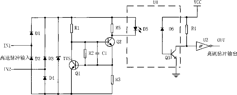
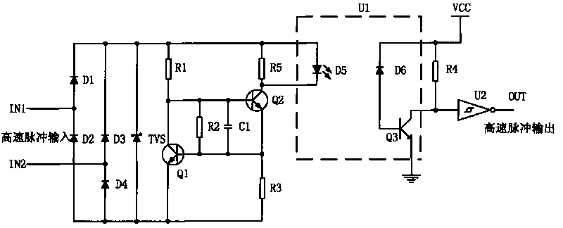
[0011] Such as figure 1 As shown, a high-speed pulse isolation transmission circuit for industrial field controllers includes a rectifier circuit, a constant current drive circuit, a high-speed optocoupler, and a Schmitt shaping circuit.

[0012] The rectifier circuit includes a first diode D1 (MMBD7000), a second diode D2 (MMBD7000), a third diode D3 (MMBD7000), a fourth diode D4 (MMBD7000) and a TVS tube (SMBJ36A). The anode of the first diode D1 is connected to the cathode of the second diode D2, the anode of the third diode D3 is connected to the cathode of the fourth diode D4; the cathode of the first diode D1, the third diode The cathode of the pole tube D3 is connected to the cathode of the TVS tube, the anode of the second diode D2 and the anode of the fourth diode D4 are connected to the anode of the TVS tube; one input terminal IN1 of the high-speed pulse is connected to the first diode D1 The anode of the second diode D2 is connected to the cathode, the other input termi


PUM


Abstract

The invention relates to a high-speed pulse isolation and transmission circuit. At present, the capacity of resisting electromagnetic interference of a technology for realizing electrical isolation is poorer. The circuit comprises a rectifying circuit, a constant current driving circuit, a high-speed optical coupler and a Schmidt shaping circuit, wherein the rectifying circuit comprises a full bridge rectifier consisting of four diodes and a TVS tube; the constant current driving circuit comprises two triodes, four resistors and a capacitor; the Schmidt shaping circuit comprises a Schmidt trigger and a resistor; the input end of the Schmidt trigger is connected with a collector electrode of a triode in the high-speed optical coupler; and the output end of the Schmidt trigger is used as the output end of the whole high-speed pulse isolation and transmission circuit. The circuit firstly carries out full bridge rectification on input alternating current pulse signals and then drives the high-speed optical coupler by using constant current, wherein the input drive current of the high-speed optical coupler basically keeps unchanged, thereby guaranteeing that the circuit has strong capacity of resisting disturbance, small signal transmission distortion and wide amplitude range of input pulse voltage.

Description


Claims


Application Information

Patent Timeline
Owner HANGZHOU DIANZI UNIV
Why Eureka
Try Eureka