Array backboard, probe used for testing array backboard and liquid crystal display panel

A technology of liquid crystal display panels and arrays, which is applied in the parts of electrical measuring instruments, measuring electricity, measuring devices, etc.

Inactive Publication Date: 2010-06-16
AU OPTRONICS CORP
View PDF0 Cites 8 Cited by
  • Summary
  • Abstract
  • Description
  • Claims
  • Application Information

AI Technical Summary

Problems solved by technology

[0005] In view of the above problems, the present invention provides an array backplane, a probe for testing the array backplane and a liquid crystal display panel, by solving the related problems caused by testing the lines of the array backplane

Method used


Image

  • Array backboard, probe used for testing array backboard and liquid crystal display panel
  • Array backboard, probe used for testing array backboard and liquid crystal display panel
  • Array backboard, probe used for testing array backboard and liquid crystal display panel

Examples


Example Embodiment

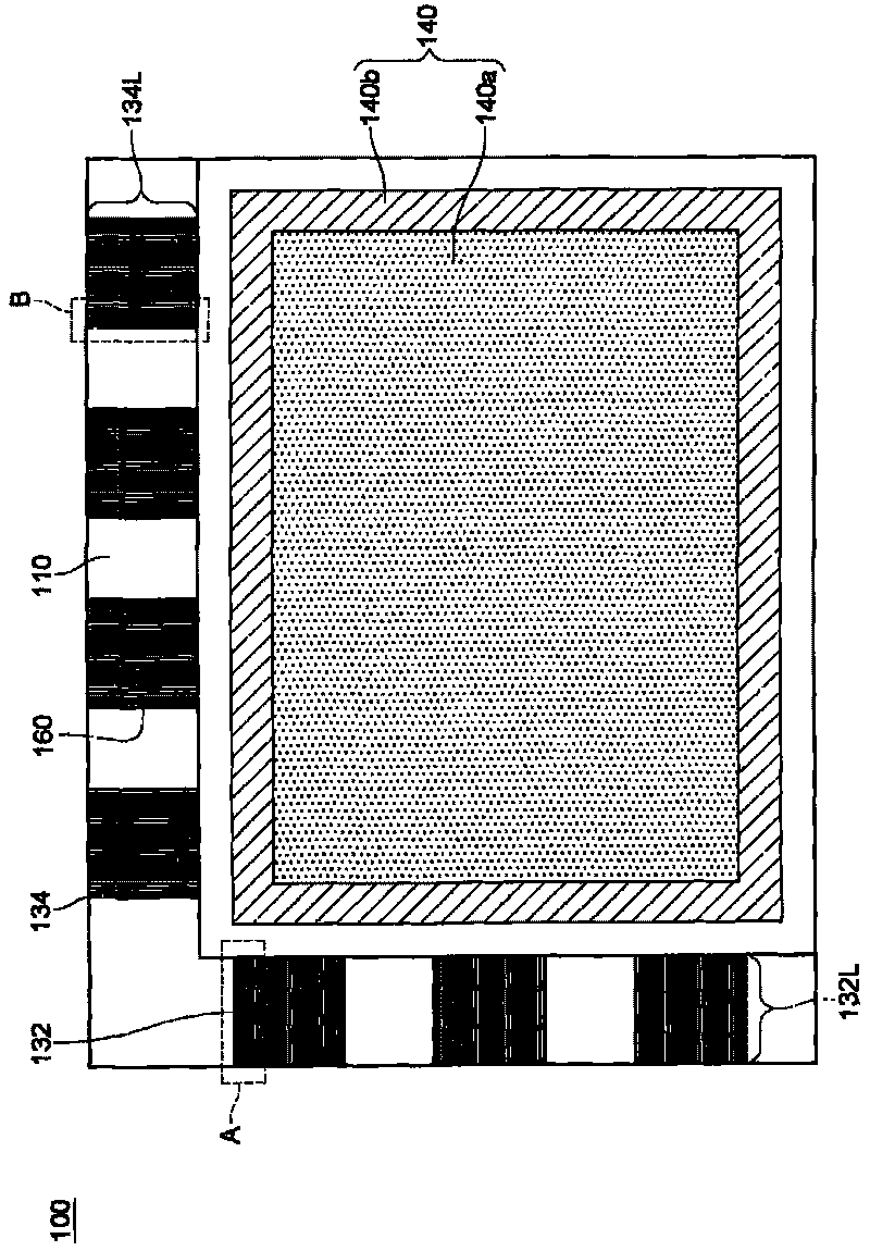
[0091] Here, conductive units are used to penetrate the covering layer (first substrate or insulating layer) of the circuit (ie, the signal line described below) to electrically conduct each circuit to the surface of the array backplane. Furthermore, the conductive units can be arranged staggered so that the output positions of signals of different signal types on the surface can be staggered horizontally or vertically. In addition, probes with strip-shaped conductive regions (hereinafter referred to as conductive strips) can be used in conjunction with the array backplane circuit detection. When detecting, only need to put the probe on the surface of the array backplane, and make the output positions of the signals of different signal types on the surface contact different conductive strips respectively.

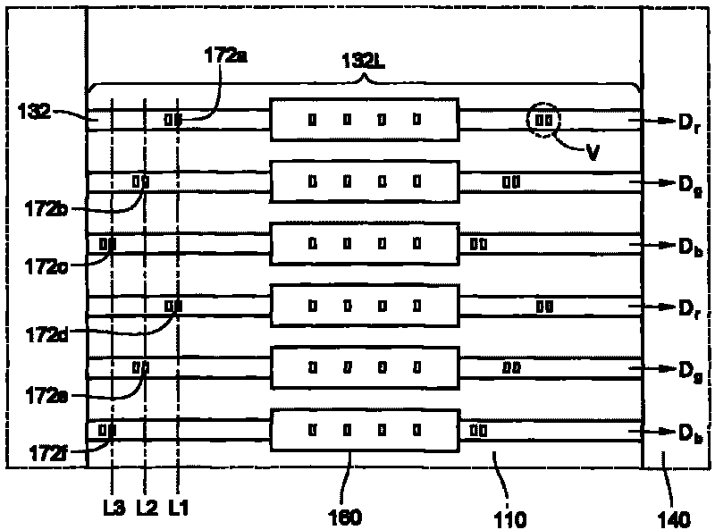
[0092] Figure 1A and Figure 1B It is a schematic diagram of an array backplane according to an embodiment of the invention. Figure 2A for Figure 1B Enlarged view of middle blo


PUM


Abstract

The invention discloses an array backboard, a probe used for testing the array backplane and a liquid crystal display panel. In the array backboard, conductive units are used to pass through a covering layer of signal wires so as to electrically conduct each signal wire to the surface of the array backboard; and the output positions of different kinds of signals on the surface are horizontally or vertically staggered through staggered configuration of the conductive units. The probe provided with strip conductive blocks (conductive bars) is matched to perform the line detection of the array backboard. During detection, the probe is only arranged on the surface of the array backboard, and the output positions of the different kinds of signals on the surface contact different conductive bars respectively. Through the device, an extender line is unnecessarily designed additionally for testing, and the line test can be easily performed on the array backboard by using the probe. After the test, the signal wires and the extender line for testing are cut without extra manufacture procedure.

Description


Claims


Application Information

Patent Timeline
Owner AU OPTRONICS CORP
Why Eureka
Try Eureka