Carrier box for polarizer

A polarizer and box technology, applied in the field of carrying boxes, can solve the problems of increased weight and difficult assembly of component products, and achieve the effect of easy assembly and reduced number of components

Active Publication Date: 2010-07-28
SHANJIN OPTOELECTRONICS SUZHOU CO LTD
View PDF0 Cites 5 Cited by
  • Summary
  • Abstract
  • Description
  • Claims
  • Application Information

AI Technical Summary

Benefits of technology

The technical effect of this patented design allows for easier installation without requiring special arrangements or components that are heavier than necessary due to the use of integrated guides along with an integral base plate attached onto top plates used during manufacturing process.

Problems solved by technology

This patented technical problem addressed in this patents relates to protecting sensitive electronic devices from shocks during shipping without compromising their accuracy when stored inside an outer container made up of multiple layers of insulating material like plastic foil laminated together.

Method used


Image

  • Carrier box for polarizer
  • Carrier box for polarizer
  • Carrier box for polarizer

Examples


Embodiment Construction

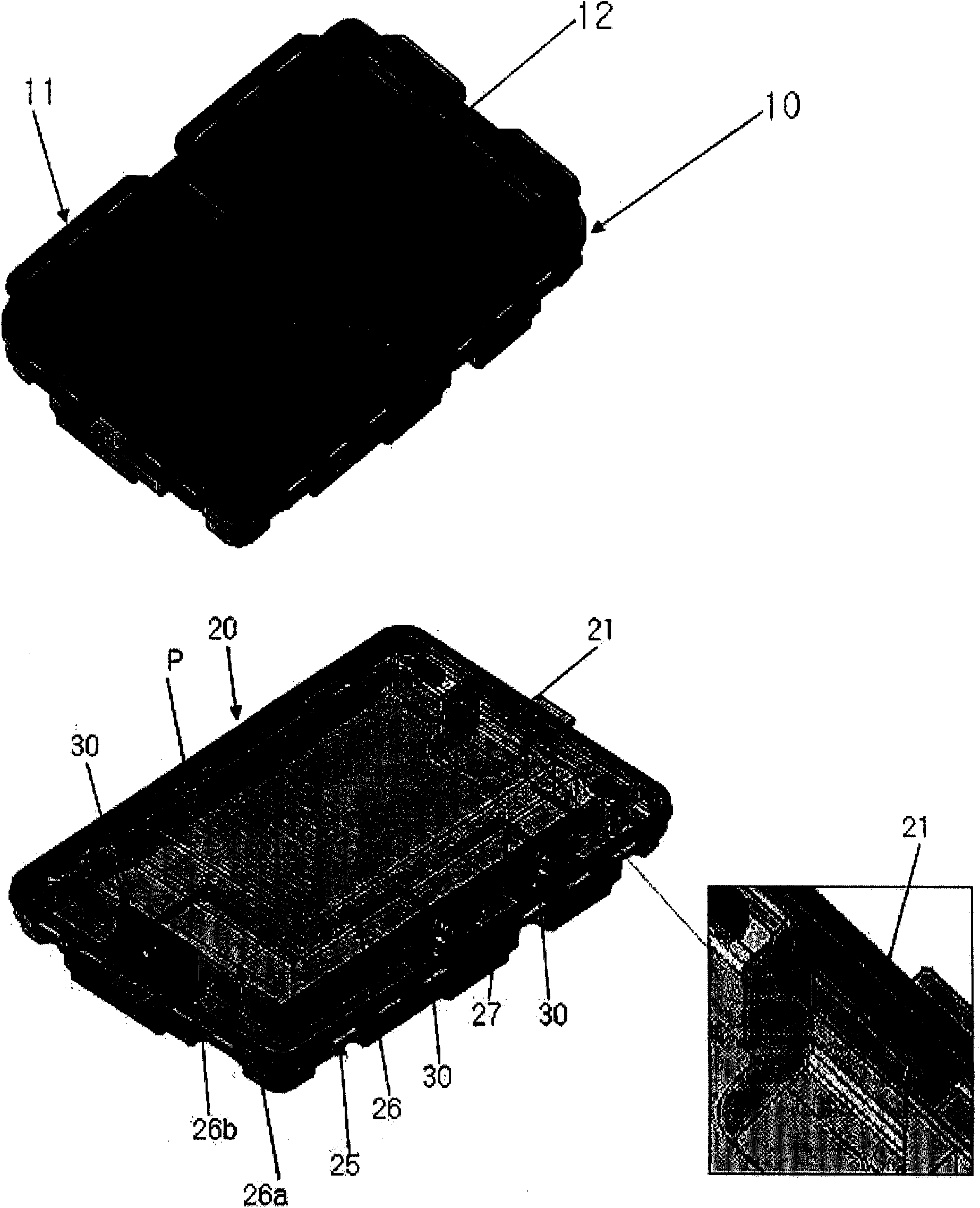
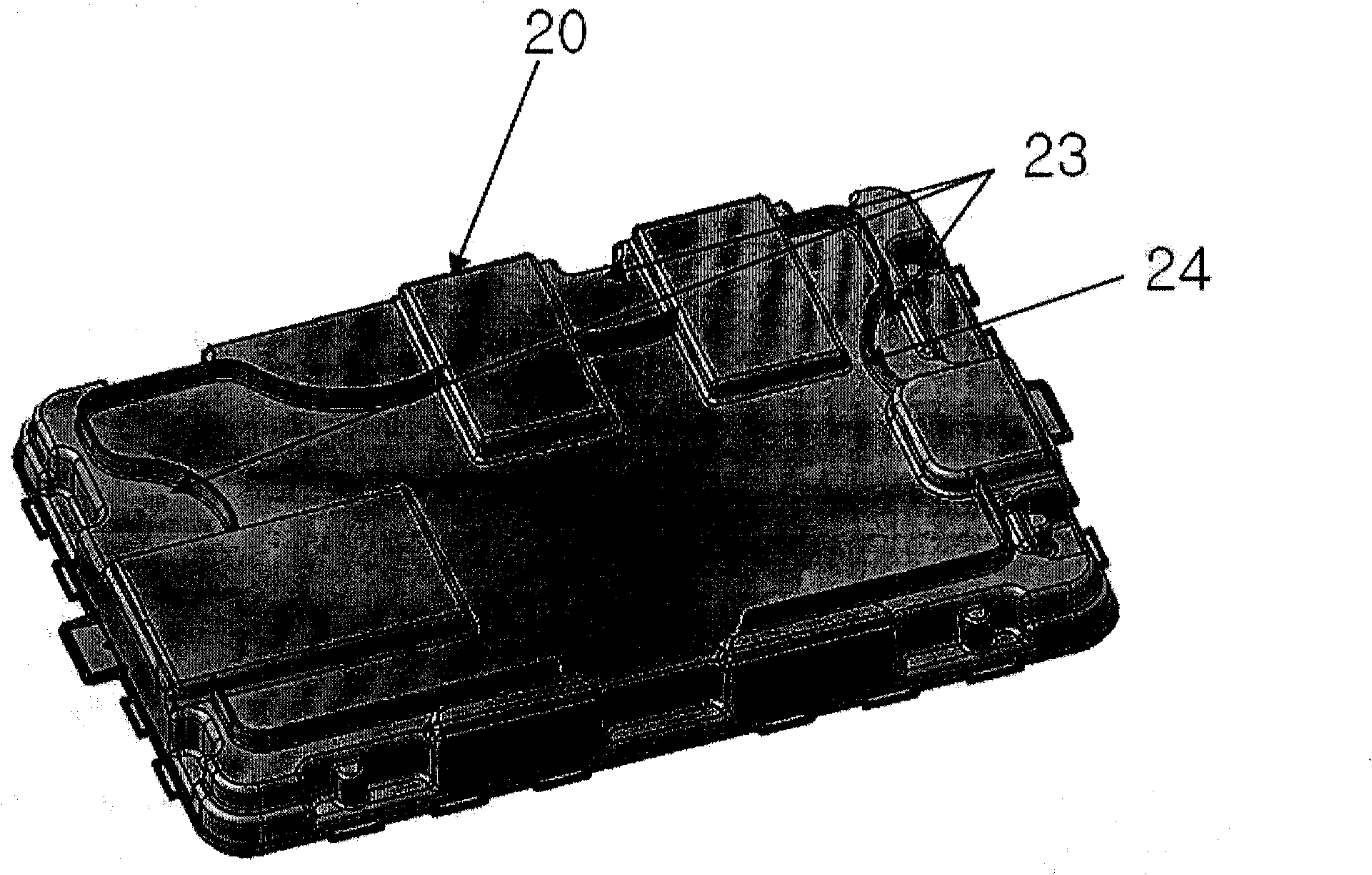
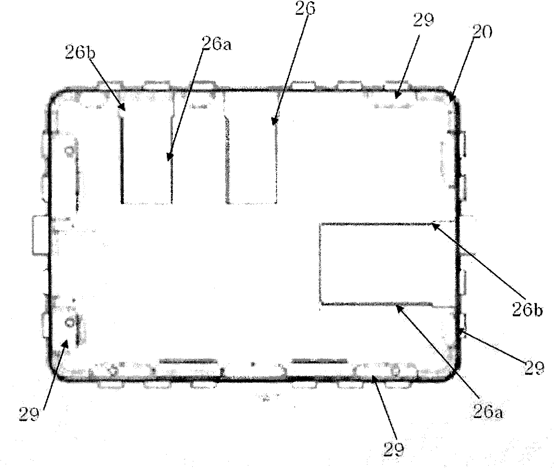
[0022] A carrying case for a polarizer, comprising: a case body having guide rails on an inner bottom plate formed in a guide groove shape and having locking walls at both sides of the inner bottom plate; and sliders having Installed in the guide rail of the case to slide along the guide rail and fixed to a predetermined position according to the size of the polarizer accommodated in the case to restrain the polarizer. The slider includes a lower moving piece inserted into the guide rail and locked to the locking wall, an upper moving piece arranged on the lower moving piece while both ends are in contact with the inner bottom plate of the box body, and clamping the lower moving piece and the upper moving piece A clamping assembly that squeezes the upper moving member and fixes it to the inner bottom plate of the box so as to limit the polarizer to a predetermined position.

[0023] A fixing groove may be formed at one side in the case to fix the polarizer accommodated in the cas


PUM


Abstract

The invention provides a carrier box for a polarizer. The carrier box comprises a box; a guide rail arranged on an inner bottom plate, wherein the guide rail is formed in a guide groove shape and locking walls are arranged at the two sides on the inner bottom plate; a slider mounted in the guide rail of the box and sliding along the guide rail and fixed at the preset position to limit the polarizer based on the size of the polarizer housed in the box, wherein the slider comprises a bottom moving piece inserted into the guide rail and locked on the locking wall, an upper moving piece arranged on the lower moving piece and contacting with the inner bottom plate at the two ends and a clamping assembly for clamping the lower moving piece and the upper moving piece and extruding the upper moving piece and fixing the upper moving piece on the inner bottom plate to limit the polarizer at the preset position.

Description


Claims


Application Information

Patent Timeline
Owner SHANJIN OPTOELECTRONICS SUZHOU CO LTD
Why Eureka
Try Eureka