Electrostatically atomizing device

A technology of electrostatic atomization and water supply device, which is applied to electrostatic spray device, electrostatic heating/cooling device, spray discharge device, etc., and can solve the problem of space limitation of electrostatic atomization device installation.

Active Publication Date: 2010-08-18
PANASONIC CORP
View PDF1 Cites 9 Cited by
  • Summary
  • Abstract
  • Description
  • Claims
  • Application Information

AI Technical Summary

Problems solved by technology

That is to say, the space where the electrostatic atomization device can be installed is limited

Method used


Image

  • Electrostatically atomizing device
  • Electrostatically atomizing device
  • Electrostatically atomizing device

Examples


Example Embodiment

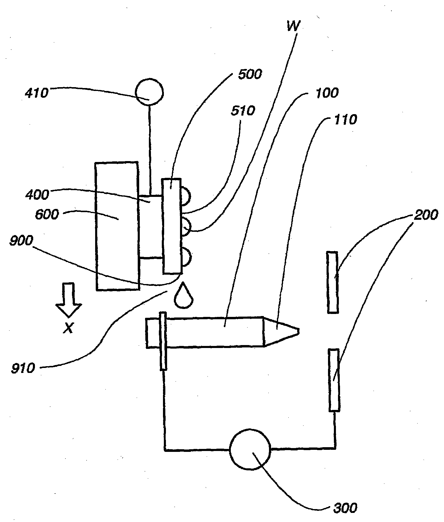
[0058] The present invention will now be explained based on the reference signs and the drawings. In addition, in Figure 1 to 15 In, the X direction is drawn to point to the direction of gravity.

[0059] figure 1 A schematic side view showing the electrostatic atomization device of the first embodiment of the present invention. The electrostatic atomization device includes an emitter electrode 100, a counter electrode 200, a high-voltage power supply 300, a Peltier module 400, a power supply 410, a heat sink 600 and a cooling plate 500. Peltier modules are limited to water supply devices. These elements are fixed to a housing not shown in the figure.

[0060] The emitter electrode 100 is formed in a rod shape, has a length along the horizontal direction, and has an emitter end at its tip. The emitter electrode is made of metal or ceramic and has a porous structure. Meanwhile, the emitter electrode may also be made of a rod-shaped metal having a felt configured to wind a rod-shap


PUM


Abstract

The invention relates to the field of industrial computer software safety, in particular to a method for encrypting and decrypting information in a memorizer and a PLC system for applying the method. The encrypting method of the invention comprises the following steps of storing an algorithm F()in the system; mapping the unique identifier of the memorizer into a cipher key K; encrypting the information stored in the memorizer by utilizing the cipher key K based on a symmetric encryption algorithm; and predefining the access strategy based on the user identity in order to control the user's access to the information stored in the memorizer; and storing the access strategy in the memorizer by utilizing the cipher key K based on the symmetric encryption algorithm. During the decryption process, decrypting, information stored in the memorizer is decrypted by utilizing the cipher key K based on the symmetric encryption algorithm, and the access strategy is decrypted by utilizing the cipher key K based on the symmetric encryption algorithm. Then the user's access to the information stored in the memorizer is controlled based on the user identity. The method and the system of the invention have the advantage of being capable of enhancing the safety of software codes.

Description


Claims


Application Information

Patent Timeline
Owner PANASONIC CORP
Why Eureka
Try Eureka