Phase locked loop and voltage controlled oscillator

A technology of voltage controlled oscillator and ring oscillator, applied in the direction of automatic power control, electrical components, etc., can solve the problems of large layout area, gain variation, and high production cost, and achieve small layout area, simple circuit structure, and low cost. Effect

Active Publication Date: 2011-05-04
PHISON ELECTRONICS
View PDF0 Cites 5 Cited by
  • Summary
  • Abstract
  • Description
  • Claims
  • Application Information

AI Technical Summary

Benefits of technology

This technology allows for precise control over an AC signal based on its own characteristics like amplitude or timing. It achieves this through adjusting certain parameters called voltages at specific points within the device's feedback path. By doing these things correctly, any variations caused during operation are corrected without affecting other parts inside the system. Overall, this technology improves performance reliability while reducing costs compared with traditional methods.

Problems solved by technology

This technical problem addressed in this patents relates to improving the stability and performance of phase-lock loops that use advanced technologies for generating signals accurately over long distances without any fluctuations or variations caused due to environmental factors including temperature and pressure differences between different locations where they may occur.

Method used


Image

  • Phase locked loop and voltage controlled oscillator
  • Phase locked loop and voltage controlled oscillator
  • Phase locked loop and voltage controlled oscillator

Examples


Embodiment Construction

[0061] The foregoing and other technical contents, features and effects of the present invention will be clearly presented in the following detailed descriptions of multiple embodiments with reference to the drawings.

[0062] Reference will now be made in detail to embodiments of the present invention, which are illustrated in the accompanying drawings. In addition, wherever possible, elements / components using the same reference numerals in the drawings and embodiments represent the same or similar parts.

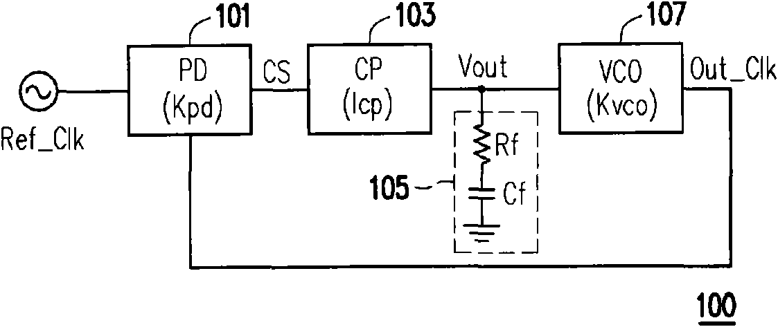
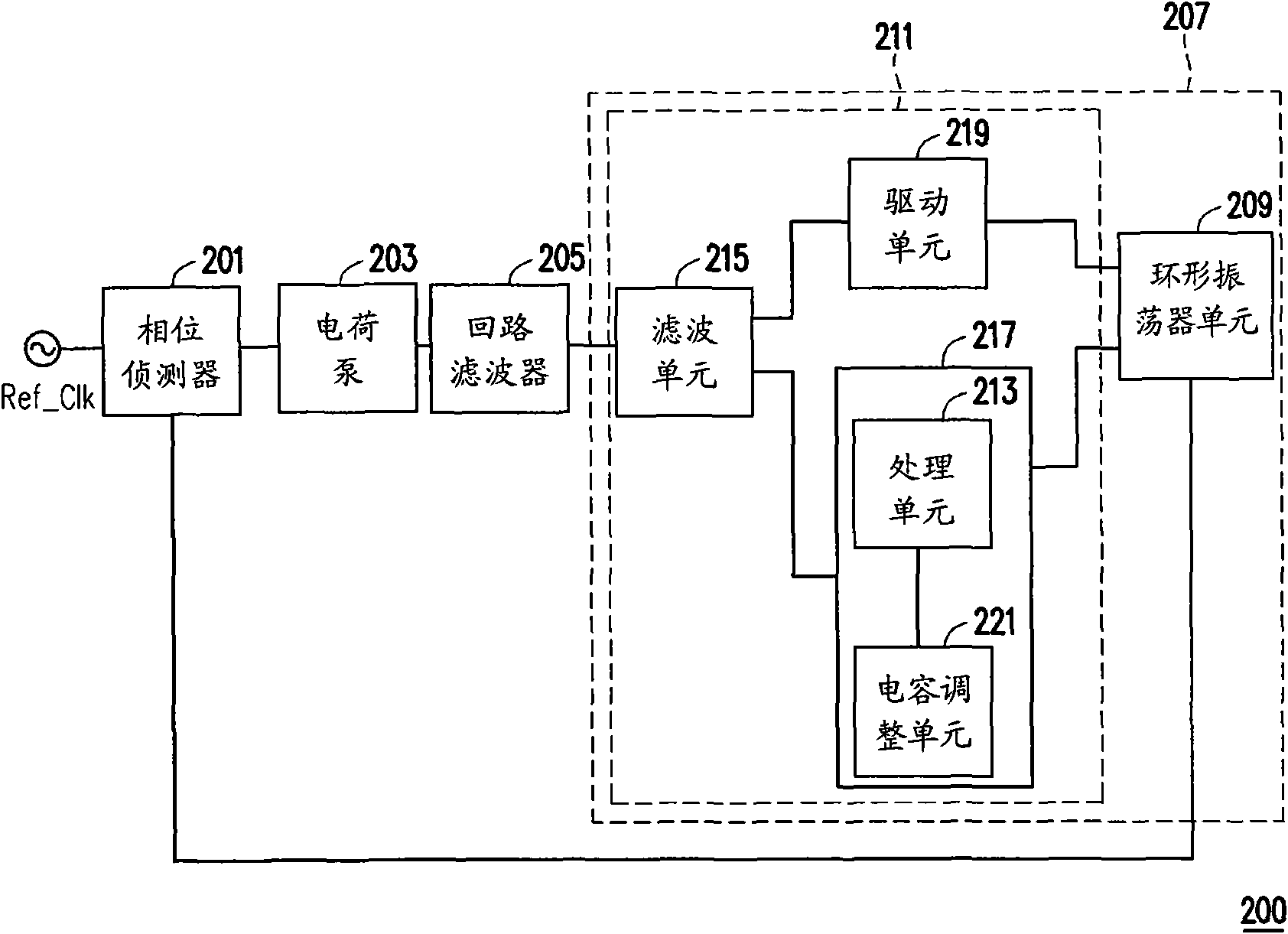
[0063] figure 2 It is a schematic block diagram of a phase-locked loop according to an embodiment of the present invention; image 3 It is a schematic circuit diagram of a phase-locked loop according to an embodiment of the present invention. Please merge reference figure 2 and image 3 , the phase locked loop (PLL) 200 includes a phase detector (phase detector, PD) 201, a charge pump (charge pump, CP) 203, a loop filter (loop filter, LP) 205, and a voltage controlled


PUM


Abstract

The invention provides a phase locked loop and a voltage controlled oscillator. The voltage controlled oscillator comprises a ring oscillator unit and a control unit, wherein the ring oscillator unit is used for providing an output clock pulse signal, the control unit is coupled with the ring oscillator unit and used for receiving an output voltage so as to respectively provide a first voltage frequency grain and a second voltage frequency grain to control the frequency of the output clock pulse signal of the ring oscillator, and the first voltage frequency grain is greater than the second voltage frequency grain.

Description


Claims


Application Information

Patent Timeline
Owner PHISON ELECTRONICS
Why Eureka
Try Eureka