Tubular infrared quartz heating lamp

A quartz heating and infrared technology, applied in the direction of ohmic resistance heating, heating element shape, electric heating device, etc., can solve the problem of low efficiency of reflected radiant heat, inability to apply tubular infrared quartz heating lamps, and heaters that cannot use blowing devices for sending hot air and other issues, to achieve simple manufacturing process, improve the efficiency of frontal heat radiation, and facilitate the effect of heat dissipation

Inactive Publication Date: 2011-05-11
柏建荣
View PDF3 Cites 0 Cited by
  • Summary
  • Abstract
  • Description
  • Claims
  • Application Information

AI Technical Summary

Problems solved by technology

When working, the heat generated by the electric heating wire in the quartz glass tube radiates to all directions. When it is applied to a heater, in order to improve the utilization rate of radiant heat from the front, it is necessary to add a mirror reflector behind the tubular infrared quartz heating lamp. Such a mirror Although the reflector can improve the utilization rate of radiant heat, the efficiency of reflecting radiant heat is very low, and the heater with mirror reflector can not use the blo

Method used


Image

  • Tubular infrared quartz heating lamp
  • Tubular infrared quartz heating lamp

Examples


Example Embodiment

[0007] In the following, the present invention will be further described through embodiments with reference to the drawings.

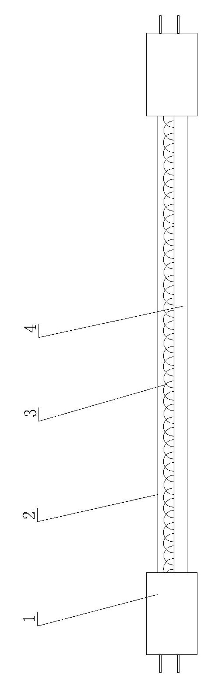
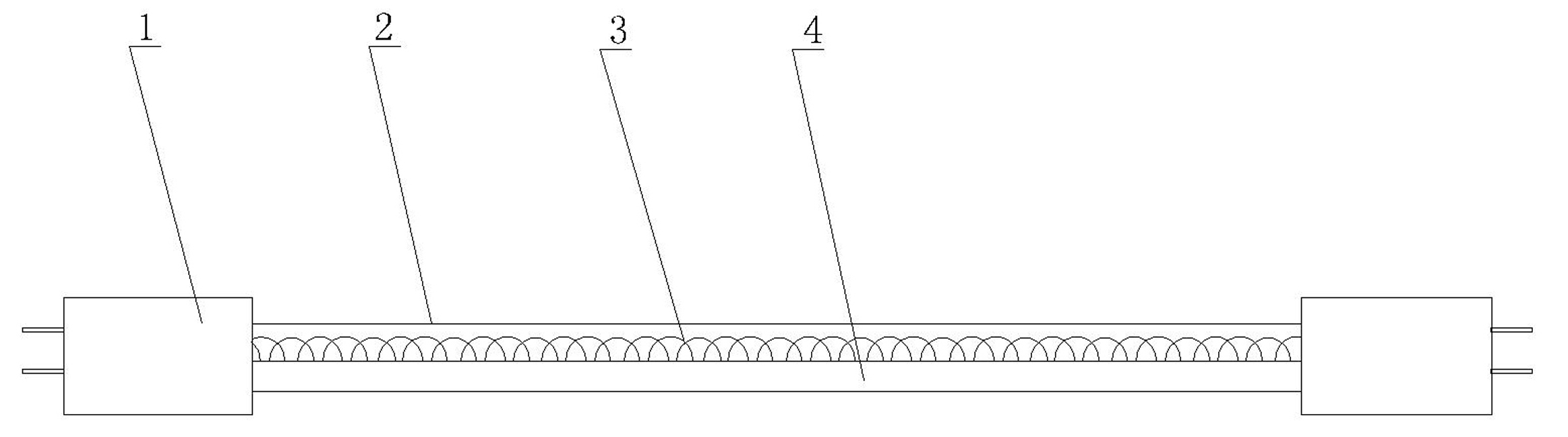
[0008] Such as figure 1 As shown, the tubular infrared quartz heating lamp of the present invention is composed of a quartz glass tube 2, a ceramic lamp holder 1 and an electric heating wire 3. The quartz glass tube 2 is an elongated round tube, and the electric heating wire 3 passes through It is placed in the evacuated quartz glass tube 2 and is characterized in that the outer surface of the quartz glass tube 2 has a nano-ceramic reflective coating 4 with a semicircular arc surface.


PUM


Abstract

The invention discloses a tubular infrared quartz heating lamp consisting of a quartz glass tube, a ceramic lamp holder and an electric heating wire, wherein the quartz glass tube is a tenuous round tube, and the electric heating wire is penetrated into the vacuumed quartz glass tube. The tubular infrared quartz heating lamp is characterized in that the outer surface of the quartz glass tube is provided with a nano ceramic reflecting coating with a semi-circular cambered surface. Because the outer surface of the quartz glass tube is provided with the nano ceramic reflecting coating with the semi-circular cambered surface, the tubular infrared quartz heating lamp provided by the invention is beneficial to radiating the heat on the nano ceramic reflecting coating, meanwhile, a smooth reflecting mirror surface is naturally generated on the reflecting surface of the nano ceramic reflecting coating attached on the outer wall of the quartz glass tube, and the smooth reflecting mirror surface has a characteristic of simple manufacturing process as comparison with an inner wall coating. The tubular infrared quartz heating lamp can remarkably improve the heat radiation efficiency of the front; and provided by tests, the tubular infrared quartz heating lamp saves power by 30 percent under the same front heat effect.

Description


Claims


Application Information

Patent Timeline
Owner 柏建荣
Why Eureka
Try Eureka