Lower spraying and cooling device arranged between finishing mill frames

A cooling device and inter-stand technology, applied in metal rolling, metal rolling, metal processing equipment, etc., can solve problems such as uneven cooling distribution, reduce temperature drop, ensure plate shape, and avoid waste of resources.

Active Publication Date: 2011-09-21
BAOSHAN IRON & STEEL CO LTD +1
View PDF5 Cites 4 Cited by
  • Summary
  • Abstract
  • Description
  • Claims
  • Application Information

AI Technical Summary

Benefits of technology

This technology uses an improved version of this type of machine called Cooling Device (CWD). It allows for precise control over how much liquid or gas flows through specific parts inside the roller's housing during processing without wasting too many materials on account of its design. By controllably changing the amount of fluid flow within certain areas along one side of the rollers, the size of these zones changes, allowing for more effective heat transfer from the material being processed. Overall, this innovation helps reduce energy usage by producing better-quality rolled products with consistently high temperatures throughout their entire length range.

Problems solved by technology

This patented technical solution described in the patents relates to improving the coolability of rollings produced with special alloys called bismuth martonitride or carburum manganite while reducing manufacturing costs associated with the installation of expensive external devices like edge heaters.

Method used


Image

  • Lower spraying and cooling device arranged between finishing mill frames
  • Lower spraying and cooling device arranged between finishing mill frames
  • Lower spraying and cooling device arranged between finishing mill frames

Examples


Embodiment 1

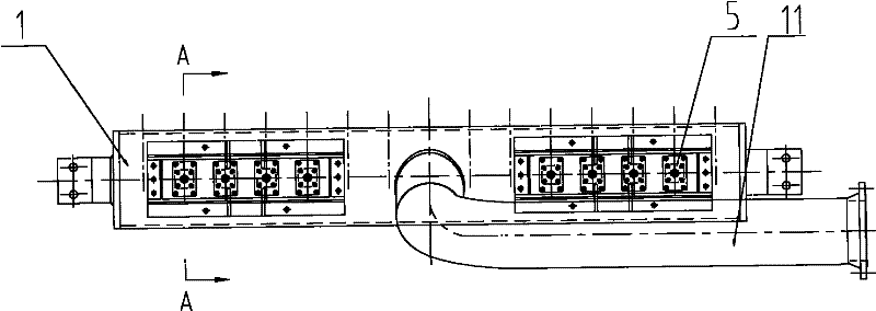
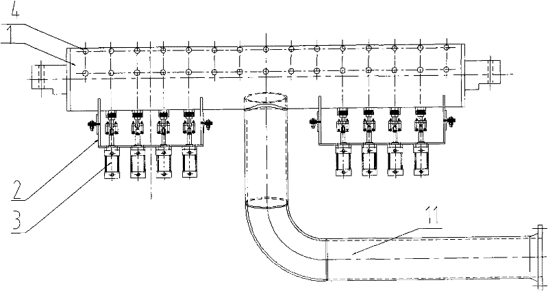
[0036] Such as Figure 2-Figure 5 As shown, the down spray cooling device between the finishing stands includes a header 1, which is arranged along the direction vertical to the running direction of the steel strip, and the water inlet pipe 11 is arranged on the header 1 and connected with it, and the central axis of the water inlet pipe 11 is connected with the There is an included angle between the horizontal central axes of the headers, and a number of discharge pipes are evenly distributed on it along the axial direction of the header 1, and each row of nozzles includes two nozzles 4, and the two nozzles 4 are arranged along the 1 Arranged in the radial direction, the two nozzle pipes 4 are connected to the header pipe 1 through their lower ends, and several sets of plunger devices 5 are respectively arranged corresponding to several nozzle discharge pipes. Wherein each set of plunger device 5 all comprises: plunger pipe 6 is correspondingly arranged under each row of spray p

Embodiment 2

[0039] Such as figure 2 , image 3 , Figure 6 and Figure 7 As shown, the downspray cooling device includes a header 1, the header 1 is arranged along the vertical running direction of the strip steel, the water inlet pipe 11 is arranged on the header 1 and communicates with it, and the central axis of the water inlet pipe 11 is horizontal to the header There is an included angle between the central axes, and a number of discharge pipes are evenly distributed on it along the axial direction of the header 1, and each row of nozzles includes two nozzles 4, and the two nozzles 4 are arranged along the radial direction of the header 1. Arranged in the same direction, the two nozzle pipes 4 are connected to the header pipe 1 through their lower ends, and several sets of plunger devices 5 are respectively arranged correspondingly to several nozzle discharge pipes. Wherein each set of plunger device 5 all comprises: plunger pipe 6 is correspondingly arranged under each row of spray


PUM


Abstract

The invention discloses a lower spraying and cooling device arranged between finishing mill frames. The lower spraying and cooling device is arranged below strip steel on the inlet side of the finishing mill frame, and comprises a collecting pipe which is arranged along the direction vertical to the running direction of strip steel, a water inlet pipe arranged on the collecting pipe, a plurality of discharging and spraying pipes, and a plurality of plunger devices; the plurality of discharging and spraying pipes are uniformly distributed above the collecting pipe along the axial direction of the collecting pipe; each row of the discharging and spraying pipes comprises a plurality of spraying pipes which are distributed along the radial direction of the collecting pipe, and each spraying pipe is communicated with the collecting pipe through a lower port; and the plurality of plunger devices correspond to the plurality of discharging and spraying pipes. Each plunger device comprises a plunger pipe with one sealed tail end, and a plunger which is arranged in the plunger pipe; the plunger pipe is provided with holes which are communicated with the spraying pipe and a water inlet whichis communicated with the collecting pipe; and the plunger can slide along the axial direction of the plunger pipe so as to block the water inlet.

Description


Claims


Application Information

Patent Timeline
Owner BAOSHAN IRON & STEEL CO LTD
Why Eureka
Try Eureka