AM wave phase-locked laser ranging method and device

A technology of laser ranging and wave locking, which is applied in the direction of measuring devices, radio wave measuring systems, electromagnetic wave reradiation, etc., can solve the problems of increasing ranging distance, decreasing signal-to-noise ratio, and inaccurate ranging results, etc., and achieves simplified structure, eliminate phase difference, and improve the effect of ranging accuracy

Inactive Publication Date: 2011-11-30
HARBIN INST OF TECH
View PDF3 Cites 12 Cited by
  • Summary
  • Abstract
  • Description
  • Claims
  • Application Information

AI Technical Summary

Problems solved by technology

The main disadvantage of the reflective ranging method is that the attenuation form of the return light signal intensity is the fourth power attenuation function of the measured distance. With the increase of the measured distance, the return light signal attenuates rapidly, resulting in a decrease in the signal-to-noise ratio. Limits the range improvement
In order to solve the above defects, the active cooperative phase laser ranging method and device (patent number: ZL200810137082) invented

Method used


Image

  • AM wave phase-locked laser ranging method and device
  • AM wave phase-locked laser ranging method and device

Examples


Embodiment Construction

[0014] The present invention will be described in detail below in conjunction with the accompanying drawings and embodiments.

[0015] 1. An AM wave phase-locked ranging method, the method may further comprise the steps:

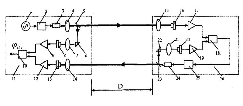
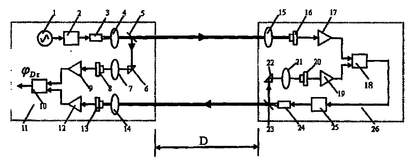
[0016] (1) At the measurement end, the sinusoidal modulation signal generated by the modulation signal generation unit acts on the laser modulation unit to modulate the light intensity of the laser beam output by the laser. One beam is directed at the target to be measured, and the other beam is used as a reference light after photoelectric conversion as a reference signal at the measurement end, denoted as E Mr ;

[0017] (2) At the measured target end, the photoelectric receiver converts the optical signal from the measuring end device into an electrical signal and then inputs it to a signal input end of the lock-in amplifier, and the output of the lock-in amplifier acts on the optical intensity modulation unit of the laser at the target end , the laser at


PUM


Abstract

The amplitude modulation wave phase-locked laser ranging method and device belong to the laser ranging technology; the present invention uses an amplitude modulated light wave phase-locked amplifier at the target end of the active phase ranging device; the measuring end of the ranging system sends a beam of light intensity through Sinusoidally modulated beam, the target end of the ranging system performs phase-locked amplification on the received amplitude modulated optical signal from the measurement end, generates a laser signal with the same modulation frequency as the laser signal from the measurement end and has a constant difference, and sends it back to the measurement end. The measurement terminal realizes the distance measurement by detecting the phase difference between the sending and receiving signals and combining the constant phase difference; it has the characteristics of high ranging accuracy.

Description


Claims


Application Information

Patent Timeline
Owner HARBIN INST OF TECH
Why Eureka
Try Eureka