Tricomponent vibration calibrating device
A calibration device and three-component technology, which is applied to measuring devices, measuring ultrasonic/sonic/infrasonic waves, instruments, etc., can solve the problems of complex data processing, difficulty in obtaining the sensitivity matrix of the inter-dimensional coupling relationship, and long time consumption
- Summary
- Abstract
- Description
- Claims
- Application Information
AI Technical Summary
Problems solved by technology
Method used
Image

Examples
Embodiment 1
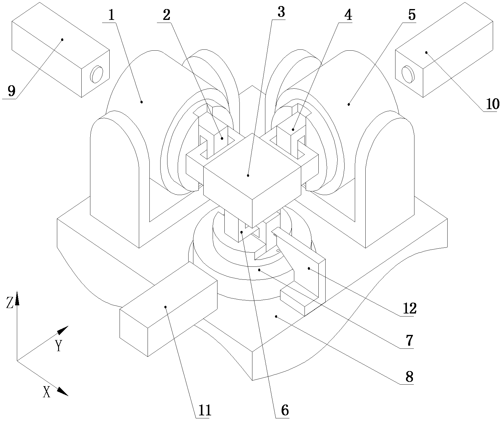
[0042] refer to figure 1 , 5 , 6, 7
[0043] The three-component vibration calibration device includes a three-component standard vibration table, and the three-component standard vibration table includes a base 8, and the X-direction electromagnetic vibration table 1 that vibrates along the X-axis is provided on the base, and vibrates along the Y-axis The Y-direction electromagnetic vibration table 5, the Z-direction electromagnetic vibration table 7 vibrating along the Z-axis, and the three-dimensional vibration platform 3 connected with the three electromagnetic vibration tables 1, 5, and 7 are placed in the three-dimensional vibration measurement sensor 30 by the school. On the three-dimensional vibration platform 3 described above;
[0044] Each axial electromagnetic vibrating table 1, 5, 7 is equipped with a laser vibrometer 9, 10, 11 to detect the axial vibration, and the vibration signal input obtained by the laser vibrometer 9, 10, 11 is In the data collector, the dat
Embodiment 2
[0065] refer to Figure 1-4
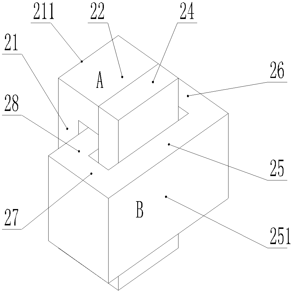
[0066] The difference between this embodiment and Embodiment 1 is that each axial electromagnetic vibrating table is connected to the three-dimensional vibrating platform 3 through motion decoupling devices 2, 4, 6 corresponding to the vibrating table;
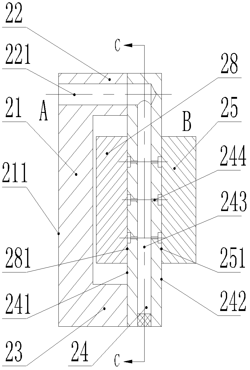
[0067] The motion decoupling device includes a first frame A and a second frame B made of rigid materials, the first frame A and the second frame B are interlocked, and the first frame and the second frame are both made of outer edges , the inner edge, the first connecting side and the second connecting side between the outer edge and the inner edge, the outer edge 21, 25 of the frame is opposite to its inner edge 24, 28 respectively, and the inner edge 24, 28 of the frame is inserted into another Inside the frame, between the outer edges 21, 25 and the inner edges 24, 28 are the first connecting sides 22, 26, and the second connecting sides 23, 27;
[0068]The inner edge 24 of the first frame is p
Embodiment 3
[0078] The difference between the present embodiment and the second embodiment is that one end of the air flow passage is sealed, and the other end is directly connected to the external compressed air source. The rest of the structures are the same.
PUM
 Abstract
Description
Claims
Application Information
 - R&D Engineer
- R&D Manager
- IP Professional
- Industry Leading Data Capabilities
- Powerful AI technology
- Patent DNA Extraction
Browse by: Latest US Patents, China's latest patents, Technical Efficacy Thesaurus, Application Domain, Technology Topic.
© 2024 PatSnap. All rights reserved.Legal|Privacy policy|Modern Slavery Act Transparency Statement|Sitemap