Protection for wind power station

a protection technology for wind power stations, applied in the direction of motors, single-network parallel feeding arrangements, reactive power adjustment/elimination/compensation, etc., can solve the problems of no use of ups systems for power stations and impact on transmission

Inactive Publication Date: 2005-10-27
PILLER GMBH
View PDF13 Cites 14 Cited by
  • Summary
  • Abstract
  • Description
  • Claims
  • Application Information

AI Technical Summary

Benefits of technology

The present invention describes a system that uses two different types of generators: one with blades attached to a rotating shaft and the other with a transmission connected to it through mechanical linkages. This allows for adjustable speeds and increases or decreases in torque depending on how fast the turbine operates. A third type of generator called an alternator has its own set of components and can be used instead of the main generator's component. It also connects to a power grid through a power converter. By connecting this generator to the power grid, the system prevents damage from accidents caused by sudden changes in voltage levels.

Problems solved by technology

The technical problem addressed in this patent is how to prevent damage to the power grid caused by faulty connections when connecting generators to the power grid due to rapid voltage fluctuation during extreme weather events like snow storms.

Method used


Image

  • Protection for wind power station
  • Protection for wind power station
  • Protection for wind power station

Examples


Embodiment Construction

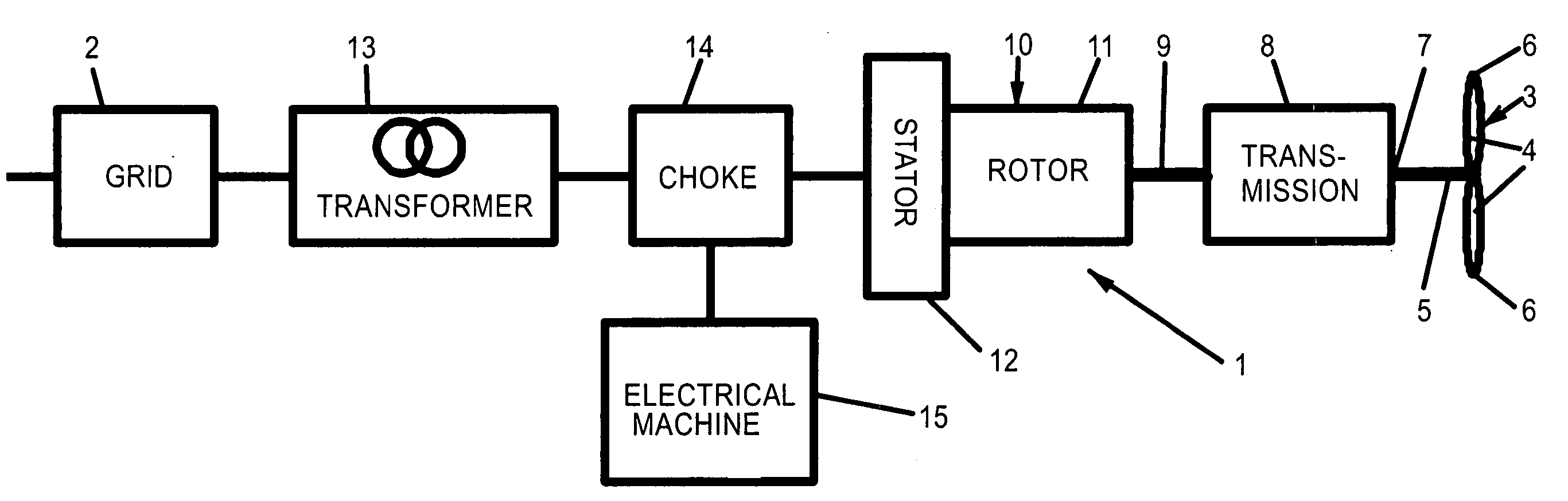
[0023] Referring now in greater detail to the drawings, FIG. 1 illustrates a wind power station 1 connected to a power grid 2. The wind power station 1 includes a wind rotor 3 having at least one, typically 2 or 3 blades 4, each of which being connected to a rotatable shaft 5. Generally, the rotatable shaft 5 is oriented horizontally at a distance to the ground which is in the order of the diameter of the wind rotor 3. Thus, the tips 6 of the blades 4 keep a distance to the ground of about half of the diameter of the wind rotor 3. The rotatable shaft 5 of the wind rotor 3 is mechanically coupled to an input shaft 7 of a transmission 8. The transmission 8 is a fixed ratio transmission increasing the rotational speed of its input shaft7 into a higher output speed of its output shaft 9. In this way the rotational speed of the wind rotor 3 is raised into an operation range of a generator 10, a rotor 11 of which is mechanically coupled to the output shaft 9 of the transmission for rotation


PUM


Abstract

A wind power station comprises a wind rotor; a transmission mechanically coupled to the wind rotor; an asynchronous generator having a generator rotor mechanically coupled to the transmission, and a generator stator electrically coupled to a power grid; and a protection unit protecting the generator and the transmission against accidental breakdowns of an alternating voltage provided by the power grid. The Protection unit includes at least one choke electrically arranged between the power grid and the generator stator, and a synchronous electrical machine electrically coupled to the choke.

Description


Claims


Application Information

Patent Timeline
Owner PILLER GMBH
Why Eureka
Try Eureka