Developing roll of laser printer and surface treatment method thereof
A technology of laser printers and developing rollers, applied in optics, coatings, instruments, etc., can solve problems such as printing bottom dust that cannot be completely solved, and achieve the effects of improving electrical performance fluctuations, reducing cleaning work, and improving roughness
- Summary
- Abstract
- Description
- Claims
- Application Information
AI Technical Summary
Problems solved by technology
Method used
Image


Examples
Embodiment 1
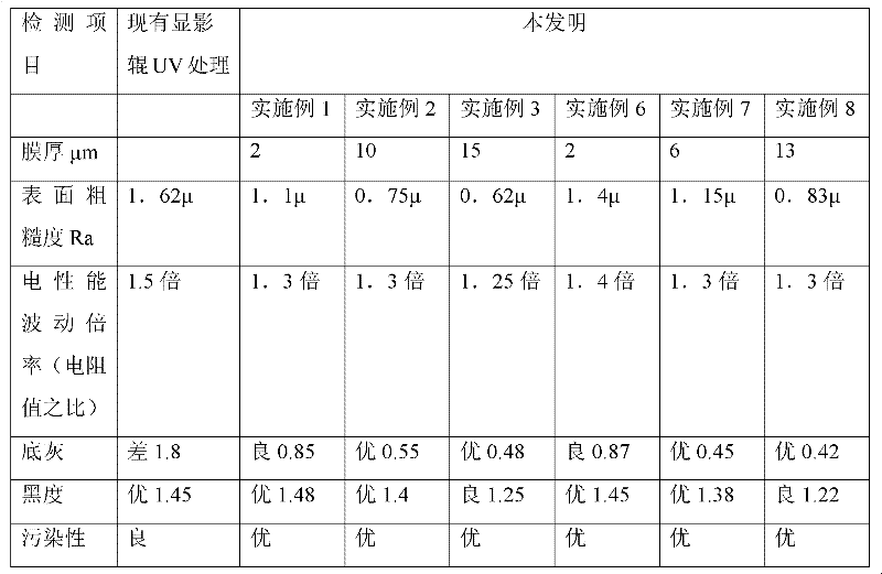
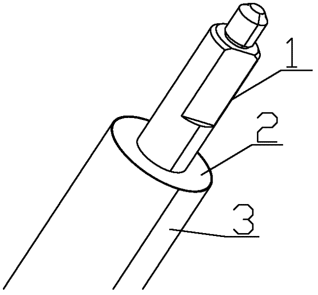
[0028] Embodiment 1, as figure 1 As shown, a developing roller for a laser printer comprises an iron core 1, an elastic body 2 wrapped around the iron core 1, and the elastic body 2 is coated with a conductive coating 3, the thickness of the conductive coating is 2 μm, and the rough The degree is 1.1μ. The iron core 1 is a cylinder, and the elastic body 2 is also a cylinder. The iron core 1 and the elastic body 2 are bonded together by an adhesive, and when the iron core 1 rotates, the elastic body 2 is driven to rotate.
[0029] The conductive coating 3 is made of the following raw materials in parts by weight: silica gel substrate coating (a mixture containing α, ω-divinyl polydimethylsiloxane with a vinyl mass fraction of 0.22%) 100. Platinum catalyst A (platinum-vinylsiloxane complex) 0.5, platinum catalyst B (blocked methylhydrogenpolysiloxane) 1.2, conductive carbon black 8.5. Among them, the silicone substrate coating is a finished product on the market. You can choose t
Embodiment 2
[0034] Embodiment 2, the structure of the developing roller is the same as that of Embodiment 1, and will not be repeated here. The thickness of the conductive coating is 10 μm. The roughness Ra of the conductive coating is 0.75μ. The conductive coating is made of the following raw materials in parts by weight: silica gel substrate coating (a mixture containing α, ω-divinyl polydimethylsiloxane with a vinyl mass fraction of 0.36%) 100 , Platinum catalyst A (platinum-vinylsiloxane complex) 0.8, platinum catalyst B (blocked methyl hydrogen polysiloxane) 1.5, conductive carbon black 9 for silica gel substrate coating. Among them, the silicone substrate coating is a finished product on the market, and the silicone coating produced by Shenzhen Chongxin Technology can be used. Platinum catalyst A and platinum catalyst B are also finished products on the market, and 25A and 25B produced by Shin-Etsu Chemical can be used.
[0035] A method for treating the surface of a developing roller
Embodiment 3
[0039] Embodiment 3, the structure of the developing roller is the same as that of Embodiment 1, and will not be repeated here. The thickness of the conductive coating is 15 μm. The roughness Ra of the conductive coating is 0.62μ. The conductive coating is made of the following raw materials in parts by weight: silica gel substrate coating (a mixture of α, ω-divinyl polydimethylsiloxane with a vinyl mass fraction of 0.60%) 100, silica gel Platinum Catalyst A (platinum-vinylsiloxane complex) 1.0, Platinum Catalyst B (blocked methylhydrogenpolysiloxane) 2.0, Conductive Carbon Black 10 for substrate coating. Wherein, the silica gel substrate coating is a ready-made product on the market, and the selection is the same as in Example 2. Platinum catalyst A and platinum catalyst B are also off-the-shelf finished products in the market, and the selection is the same as in Example 2.
[0040] A method for treating the surface of a developing roller of a laser printer, comprising the foll
PUM
| Property | Measurement | Unit |
|---|---|---|
| Thickness | aaaaa | aaaaa |
| Roughness | aaaaa | aaaaa |
| Thickness | aaaaa | aaaaa |
Abstract
Description
Claims
Application Information
 - R&D Engineer
- R&D Manager
- IP Professional
- Industry Leading Data Capabilities
- Powerful AI technology
- Patent DNA Extraction
Browse by: Latest US Patents, China's latest patents, Technical Efficacy Thesaurus, Application Domain, Technology Topic.
© 2024 PatSnap. All rights reserved.Legal|Privacy policy|Modern Slavery Act Transparency Statement|Sitemap