Automobile hand brake fatigue test rack

A fatigue test, hand braking technology, applied in vehicle testing, mechanical component testing, machine/structural component testing, etc. Equipment can not meet the requirements of the new standard and other problems, to achieve the effect of strong versatility

Active Publication Date: 2012-04-25
ANHUI DACHANG TECH
View PDF7 Cites 14 Cited by
  • Summary
  • Abstract
  • Description
  • Claims
  • Application Information

AI Technical Summary

Benefits of technology

This technology allows for coordinated control over an upward movement of multiple parts within one machine or system. It achieves these goals through use of timing relays with magnetically operated regulators, which are designed specifically for testing purposes. By controlling the rising speed at different points along its path, it ensures full loads have been applied onto both teeth during assembly. Additionally, there may also include a mechanism called a tensioner to maintain proper tightness between components such as gears. Overall, this technology provides flexibility and ease of implementation across various industries while still providing effective performance capabilities.

Problems solved by technology

This patented testing device cannot accurately simulate different levels or types of stress during vehicle operation due to its limitations with regard to loads that may cause damage to certain parts of the mechanism used for driving it. Additionally, current devices have issues controlling how fast they start up when loaded too much pressure onto them causing wear out overtime.

Method used


Image

  • Automobile hand brake fatigue test rack
  • Automobile hand brake fatigue test rack
  • Automobile hand brake fatigue test rack

Examples


Embodiment Construction

[0030] With reference to the accompanying drawings, the specific implementation of the present invention will be further described in detail through the description of the embodiments to help those skilled in the art have a more complete, accurate and in-depth understanding of the inventive concept and technical solution of the present invention.

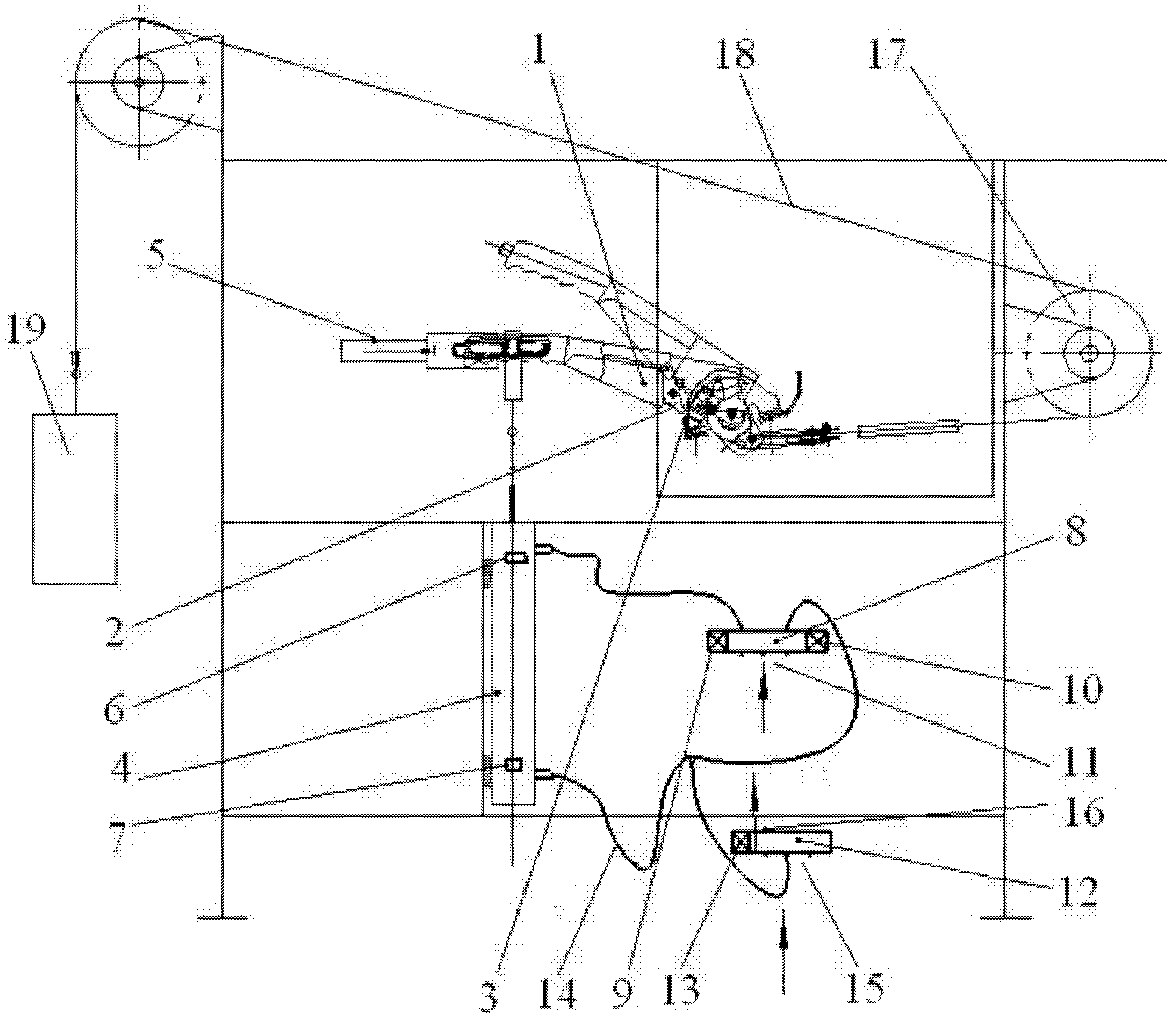
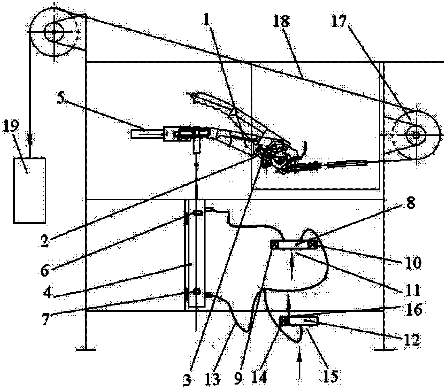
[0031] Such as figure 1 , figure 2 The structure of the present invention expressed is an automobile hand brake fatigue test bench, which is used for the fatigue test of the test sample 1 of the hand brake. The test sample 1 includes a ratchet wheel 2, a tooth plate 3, and The test bench described is provided with a traction cable 18, a traction pulley 17 and a traction weight 19, and the test bench is also provided with a hand brake control cylinder 4 and a hand brake button cylinder 5. The invention is proposed for improving the automobile hand brake fatigue test bench.

[0032] The traction cable 18, the traction pulley 17 and the trac


PUM


Abstract

The invention discloses an automobile hand brake fatigue test rack. The test rack is provided with a traction cable (18), a traction pulley (17), a traction poise (19), a hand brake operating cylinder (4) and a hand brake button cylinder (5), wherein a time relay and a travel switch are arranged in a control circuit of the automobile hand brake fatigue test rack; and the travel switch is a limit position travel switch of the hand brake operating cylinder (4). By using the technical scheme, the ascending process of the cylinder is controlled by the time relay and the travel switch together, and the ascending time of the cylinder is controlled by the time relay; a deflation device is adopted during loading of force on a ratchet and a tooth plate to guarantee that the load is fully loaded onthe ratchet and the tooth plate; the loading time is controlled by the time relay and can be flexibly adjusted according to a standard requirement; and the test rack has high universality and is suitable for generalization and application.

Description


Claims


Application Information

Patent Timeline
Owner ANHUI DACHANG TECH
Why Eureka
Try Eureka