Photocatalyst light emitting diode lamp

A technology of light-emitting diodes and photocatalysts, applied to light sources, point light sources, lighting and heating equipment, etc., can solve problems such as high production and production costs, inconspicuous sterilization and deodorization, and complicated assembly and production processes of photocatalyst light-emitting diode lamps, etc., to achieve The effect of reducing production costs and simplifying the production process

Inactive Publication Date: 2012-06-06
CWHLED OPTICAL CORP
View PDF0 Cites 4 Cited by
  • Summary
  • Abstract
  • Description
  • Claims
  • Application Information

AI Technical Summary

Benefits of technology

This technology allows for better protection against environmental factors such as water vapor or dust during use. It also makes sure that there's no harmful substances like ozone gas inside when used with LED lights. Additionally, this technology helps prevent damage caused by excessive heat on electronic devices due to improperly designed components.

Problems solved by technology

This patented technology describes how different types of materials like silicon carbons and organic compounds were added during the fabrication of various electronic devices including LCD displays. These new components help reduce harmful environmental impact caused by certain gases released from them while still providing useful properties like cleanlinability, germination resistance, antimicrobial activity. However, this approach requires expensive equipment and complex processes involving multiple steps before final product formation.

Method used


Image

  • Photocatalyst light emitting diode lamp
  • Photocatalyst light emitting diode lamp
  • Photocatalyst light emitting diode lamp

Examples


Embodiment Construction

[0020] Below in conjunction with accompanying drawing and embodiment the present invention is described in detail:

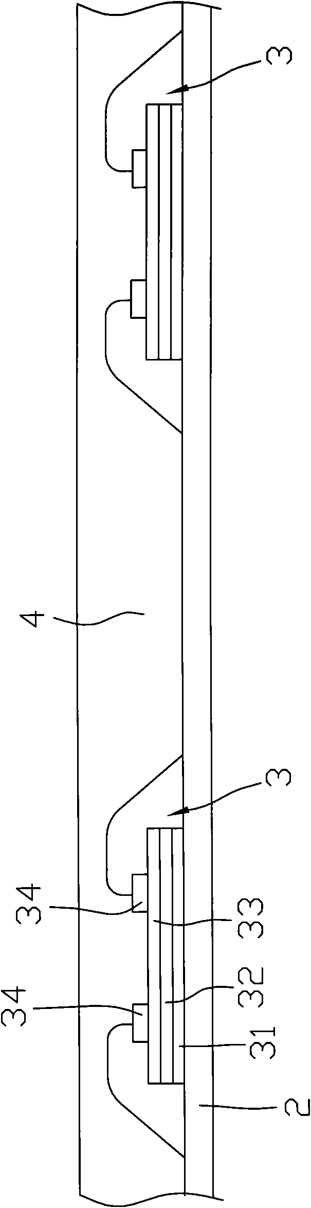
[0021] refer to figure 2 A first preferred embodiment of the photocatalyst light-emitting diode lamp of the present invention comprises a substrate 2, at least one light-emitting diode 3 arranged on the substrate 2, and a layer of photocatalyst formed upward from the substrate 2 for encapsulating the light-emitting diode 3 Layer 4.

[0022] The light emitting diode 3 includes a substrate 31 connected to the substrate 2 , an epitaxial layer 32 extending upward from the substrate 31 , and a transparent conductive layer 33 formed on the epitaxial layer 32 , and two electrodes 34 for electrically connecting with the substrate 2 and electrically connecting with the epitaxial layer body 32 and the transparent conductive layer 33 respectively. It should be noted that a plurality of light emitting diodes 3 are schematically shown in the figure , those skilled in the art


PUM

PropertyMeasurementUnit
Wavelengthaaaaaaaaaa

Abstract

The invention provides a photocatalyst light emitting diode lamp. The lamp comprises a substrate, at least one light emitting diode arranged on the substrate, and a transparent photocatalyst layer which is formed above the substrate to isolate the light emitting diode from the outside, wherein when electric energy is supplied to the light emitting diode through the substrate to enable the light emitting diode to emit light, the photocatalyst layer is excited by the light produced by the light emitting diode to produce high-energy electron hole pair to achieve the effects of sterilization, deodorization and self-cleaning. According to the photocatalyst light emitting diode lamp, the light emitting diode is directly encapsulated by the photocatalyst layer and isolated from pollutants and vapor of the outside, so that the manufacture process is simplified, and the product cost is reduced.

Description


Claims


Application Information

Patent Timeline
Owner CWHLED OPTICAL CORP
Why Eureka
Try Eureka