Process for machining water-cooling plate of high-power waveguide component

A processing technology and water-cooling plate technology, applied in metal processing equipment, manufacturing tools, auxiliary devices, etc., can solve the problems of reduced reliability, residual chips in the water tank, shortened service life of waveguide components, etc., and achieve the effect of improving accuracy

Inactive Publication Date: 2012-10-03
YANGZHOU HENGXING PRECISION MACHINERY
View PDF6 Cites 10 Cited by
  • Summary
  • Abstract
  • Description
  • Claims
  • Application Information

AI Technical Summary

Problems solved by technology

But another serious technical problem brought by this is that the chips generated during the tapping process will inevitably remain in the water tank. At present, it is generally washed by high-pressure air, but practice has proved that it is difficult to completely remove
These debris will seriously damage the operating sy

Method used


Image

  • Process for machining water-cooling plate of high-power waveguide component
  • Process for machining water-cooling plate of high-power waveguide component
  • Process for machining water-cooling plate of high-power waveguide component

Examples


Embodiment Construction

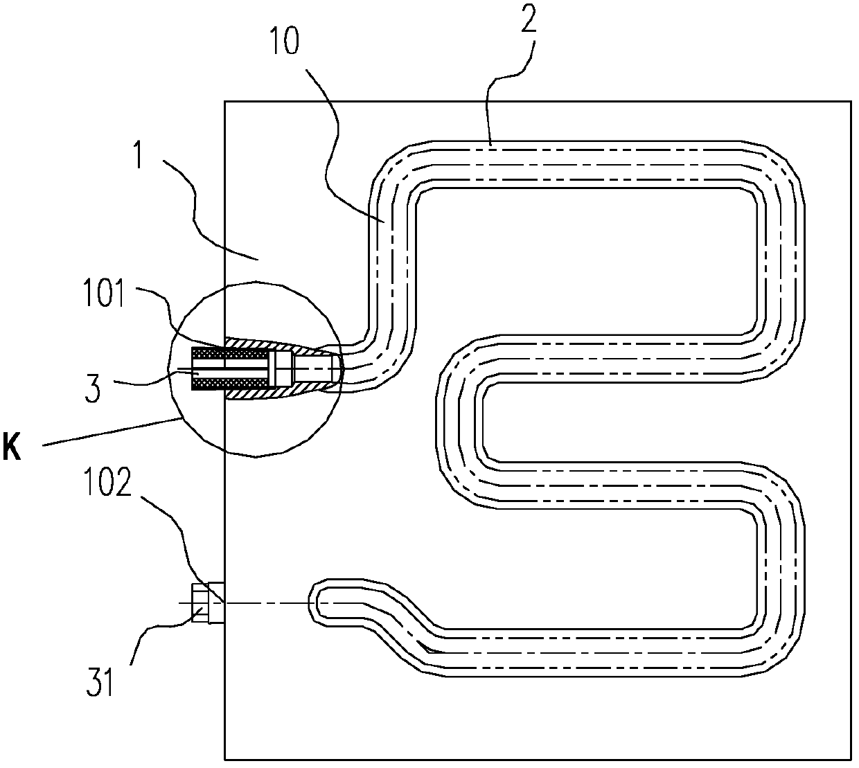
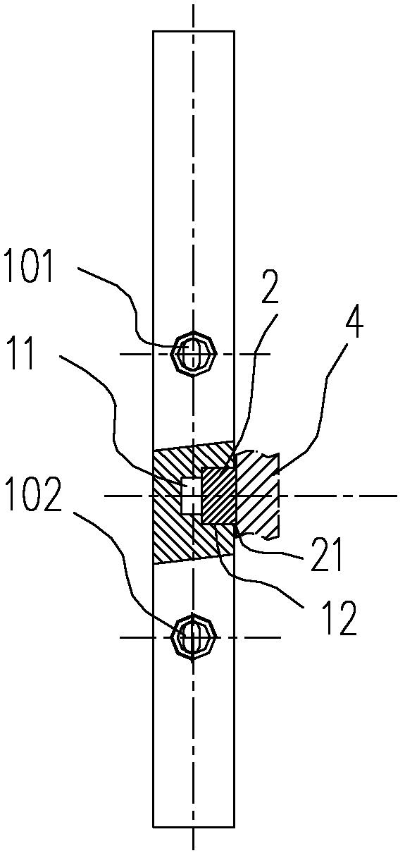
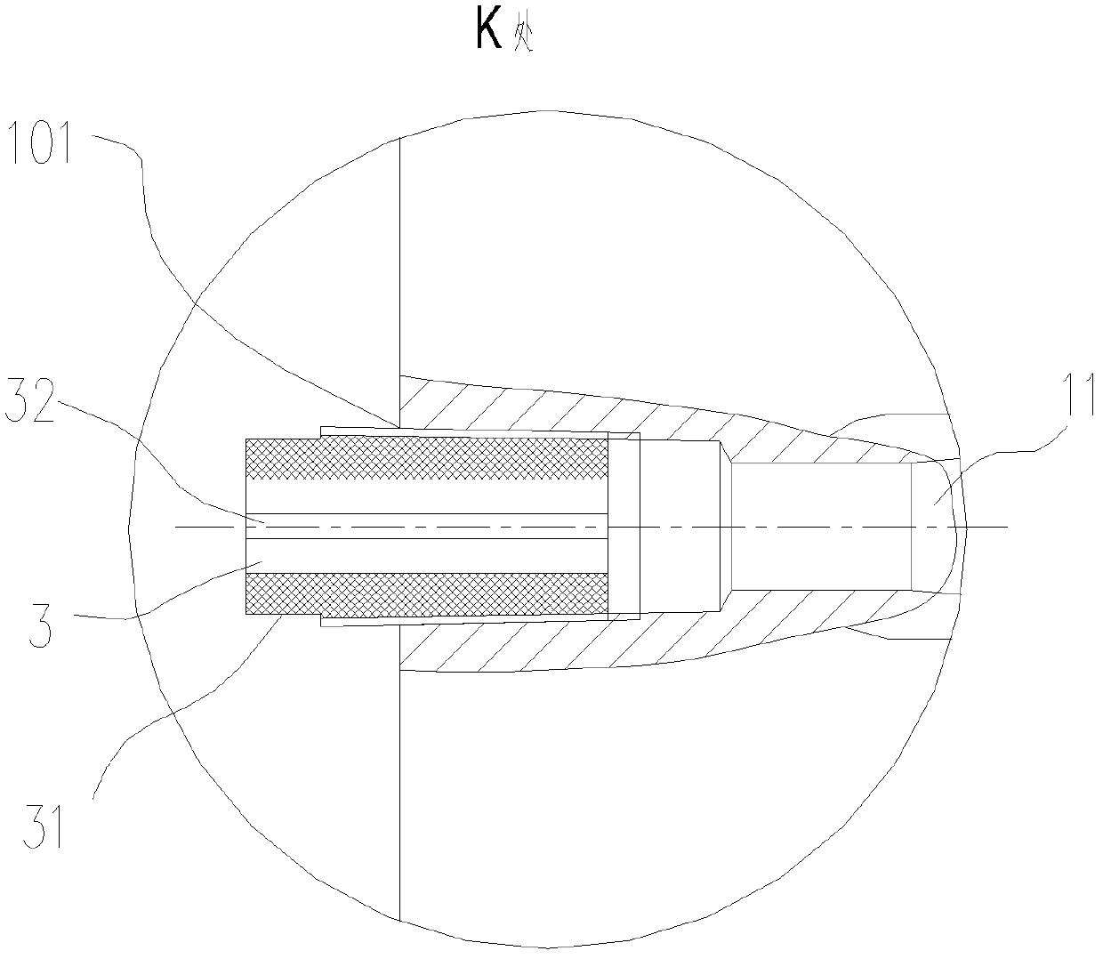
[0015] The present invention as Figure 1-4 As shown, the following steps are included: opening a meandering water tank 10 from the top surface of the water-cooling plate 1; opening threaded water inlets and outlets (including water port 101 and water port 2 102) from the side of the water-cooling plate 1, respectively communicating The water tank 10; the sealing plate 2 is added to the water tank 10 by vacuum brazing; before brazing, the ceramic threaded pipe 2 is respectively screwed into the threaded holes of the water inlet and outlet; after brazing, remove The ceramic threaded pipe 2.

[0016] The inner surface of the hole of the ceramic threaded pipe 2 is provided with an axial groove 32; so as to facilitate crushing;

[0017] The root of the ceramic threaded pipe 2 is provided with an outer hexagonal square opening 31 or an inner hexagonal square opening; so as to facilitate screwing in and out.

[0018] The water tank 10 is convex, with a small opening inside and a larg


PUM


Abstract

The invention relates to a process for machining a water-cooling plate of a high-power waveguide component, and provides a process for machining the water-cooling plate of the high-power waveguide component, which can guarantee the flatness of a finished product and can prevent residual tapping cuttings from being left. The process comprises the following steps of: forming a zigzag water channel on the top surface of the water-cooling plate; forming a water inlet and a water outlet which are provided with threads on the side surface of the water-cooling plate, and communicating the water inlet and the water outlet with the water channel respectively; adding a solder sealing plate on the water channel through vacuum brazing; before brazing, screwing a ceramic threaded pipe into threaded holes of the water inlet and the water outlet respectively; and after brazing, removing the ceramic threaded pipes. By the process, the conventional one-step machining mode is changed, and the problems of incapability of compaction, dents of the sealing plate and the tapping cuttings left in the water channel, which always exist in the prior art, are effectively solved; and the accuracy and the reliability of the finished product are greatly improved.

Description


Claims


Application Information

Patent Timeline
Owner YANGZHOU HENGXING PRECISION MACHINERY
Why Eureka
Try Eureka