Method and apparatus for defining transceiving timing of a physical channel in a TDD communication system which supports cross-carrier schedulin
A cross-carrier scheduling and physical channel technology, applied in the field of cellular wireless communication systems, to reduce transmission errors and transmission delays
- Summary
- Abstract
- Description
- Claims
- Application Information
AI Technical Summary
Benefits of technology
Problems solved by technology
Method used
Image

Examples
no. 1 example
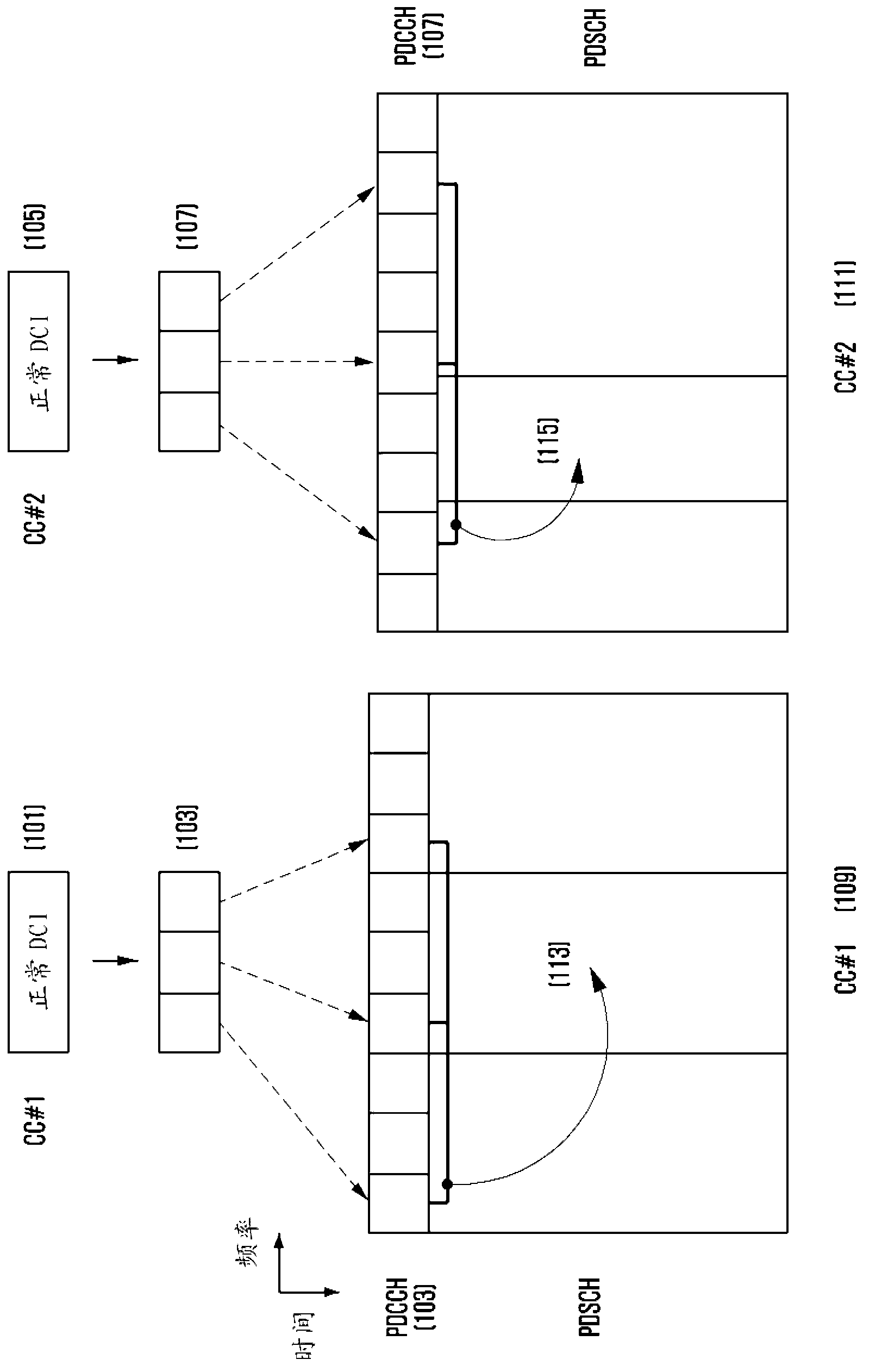
[0092] The first embodiment describes a method for defining PDCCH, PDSCH associated with downlink data transmission when aggregated carriers are configured to have different TDD uplink-downlink configurations in a TDD wireless communication system supporting carrier aggregation and UL HARQ ACK / NACK timing relationship method.
[0093] reference below Figure 5 Examples are described in detail.
[0094] Figure 5 An example of a TDD system operating with two aggregated carriers is shown: CC1 501 with TDD uplink-downlink configuration #2 and CC2 503 with TDD uplink-downlink configuration #6. Although in Figure 5 In the targeted example, CC1 and CC2 have the same frame timing, but the present invention is applicable to cases where the radio frame timings of the component carriers do not match each other.
[0095] exist Figure 5 In , the PDSCH scheduling operation on CC1 (that is, the operation that rules out (ruled out) the cross-carrier scheduling) is the same as that in t
no. 2 example
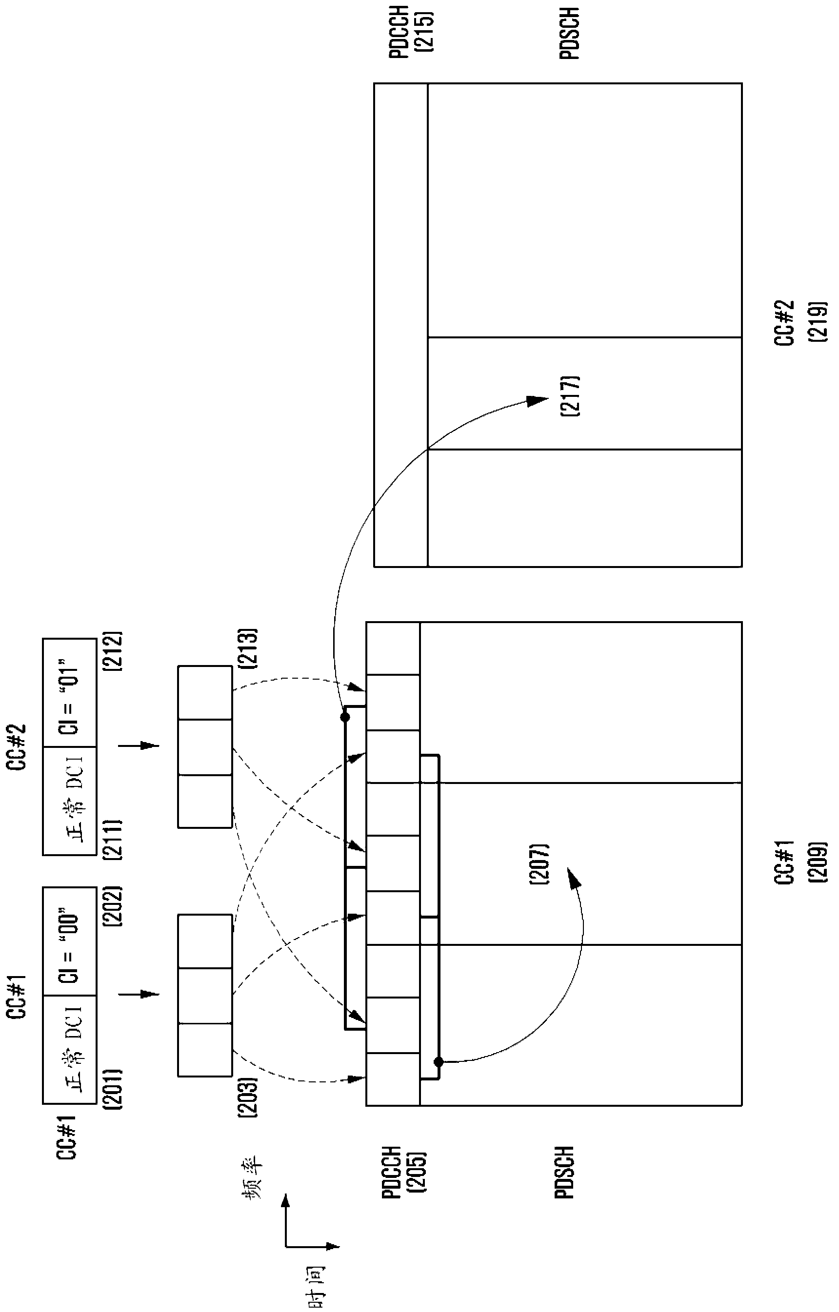
[0109] The second embodiment describes a method for defining PDCCH, PDSCH associated with downlink data transmission when aggregated carriers are configured with different TDD uplink-downlink configurations in a TDD wireless communication system supporting carrier aggregation Another approach to the timing relationship between UL HARQ ACK / NACK and UL HARQ ACK / NACK.
[0110] Reference below Figure 8 example to describe in detail.
[0111] Figure 8 An example of a TDD system operating with two aggregated component carriers is shown: CC1 801 with TDD uplink-downlink configuration #2 and CC2 803 with uplink-downlink configuration #6. Although in Figure 8 In the targeted example, CC1 and CC2 have the same frame timing, but the present invention is applicable when the radio frame timings of the component carriers do not match each other.
[0112] exist Figure 8 In , the PDSCH scheduling operation on CC1 (ie, the operation excluding cross-carrier scheduling) is the same as
no. 3 example
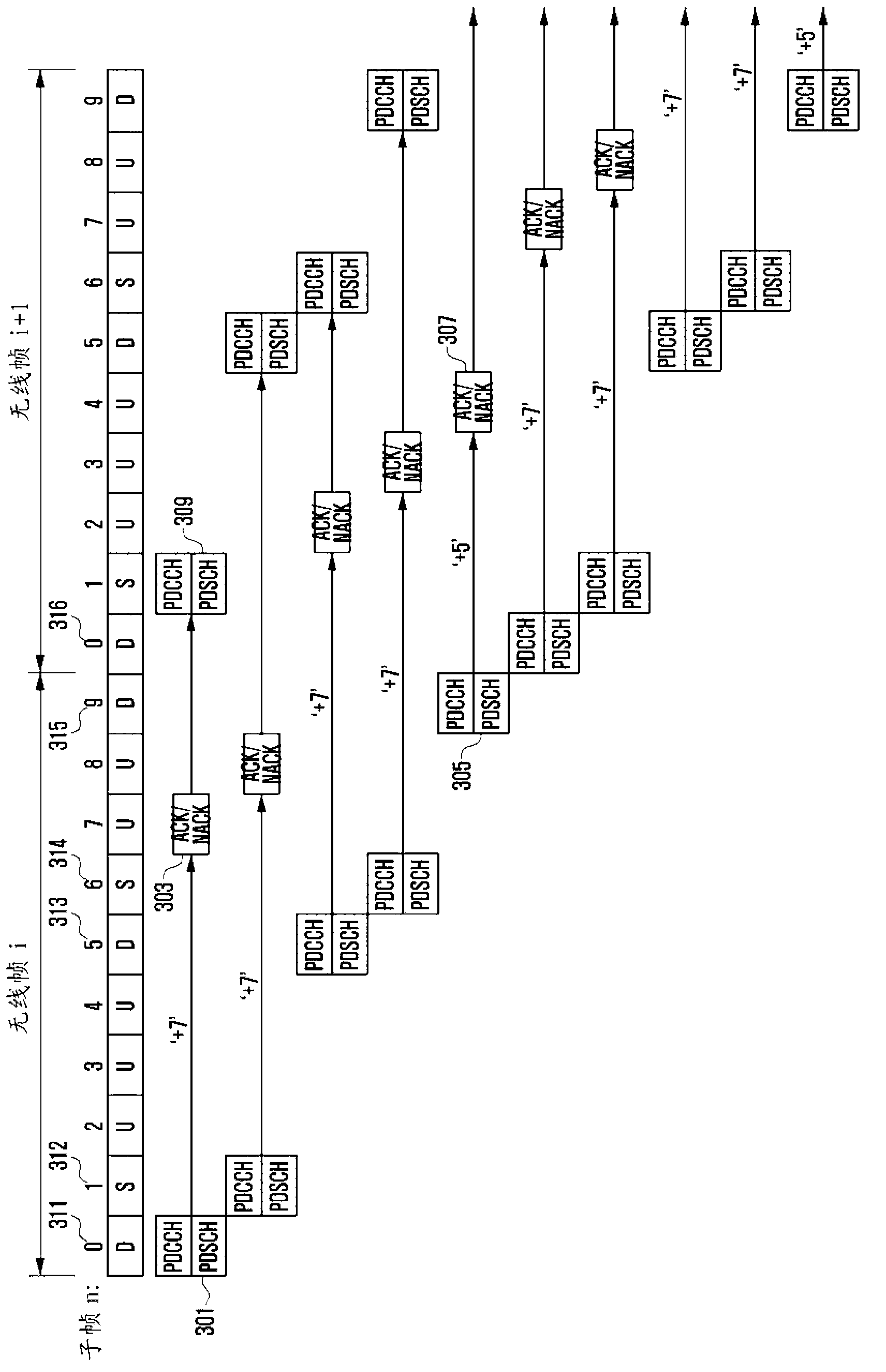
[0123] The third embodiment describes a method for defining a link associated with uplink data transmission in a TDD wireless communication system obtaining wide bandwidth through carrier aggregation, especially when aggregated carriers are configured to have different TDD uplink-downlink configurations. The method of the timing relationship among PDCCH, PUSCH and PHICH.
[0124] Reference below Figure 11 Examples are described in detail.
[0125] Figure 11 An example of a TDD system operating with two aggregated component carriers is shown: CC1 1101 with TDD uplink-downlink configuration #3 and CC2 1103 with uplink-downlink configuration #3. Although in Figure 11 In the targeted example, CC1 and CC2 have the same frame timing, but the present invention is applicable when the radio frame timings of the component carriers do not match each other.
[0126] The LTE system employs synchronous HARQ with fixed data transmission timing in uplink. Accordingly, the uplink / downli
PUM
 Abstract
Description
Claims
Application Information
 - R&D Engineer
- R&D Manager
- IP Professional
- Industry Leading Data Capabilities
- Powerful AI technology
- Patent DNA Extraction
Browse by: Latest US Patents, China's latest patents, Technical Efficacy Thesaurus, Application Domain, Technology Topic.
© 2024 PatSnap. All rights reserved.Legal|Privacy policy|Modern Slavery Act Transparency Statement|Sitemap