Magnetostrictive open circuit optical control device
An optical control and magnetostrictive technology, applied in measurement devices, protection against overcurrent, instruments, etc., can solve the problems of complex signal processing, complex circuit structure, malfunction, etc., and achieve fast response speed and reliability. High, less error-introduced effect
- Summary
- Abstract
- Description
- Claims
- Application Information
AI Technical Summary
Problems solved by technology
Method used
Image

Examples
specific Embodiment approach 1
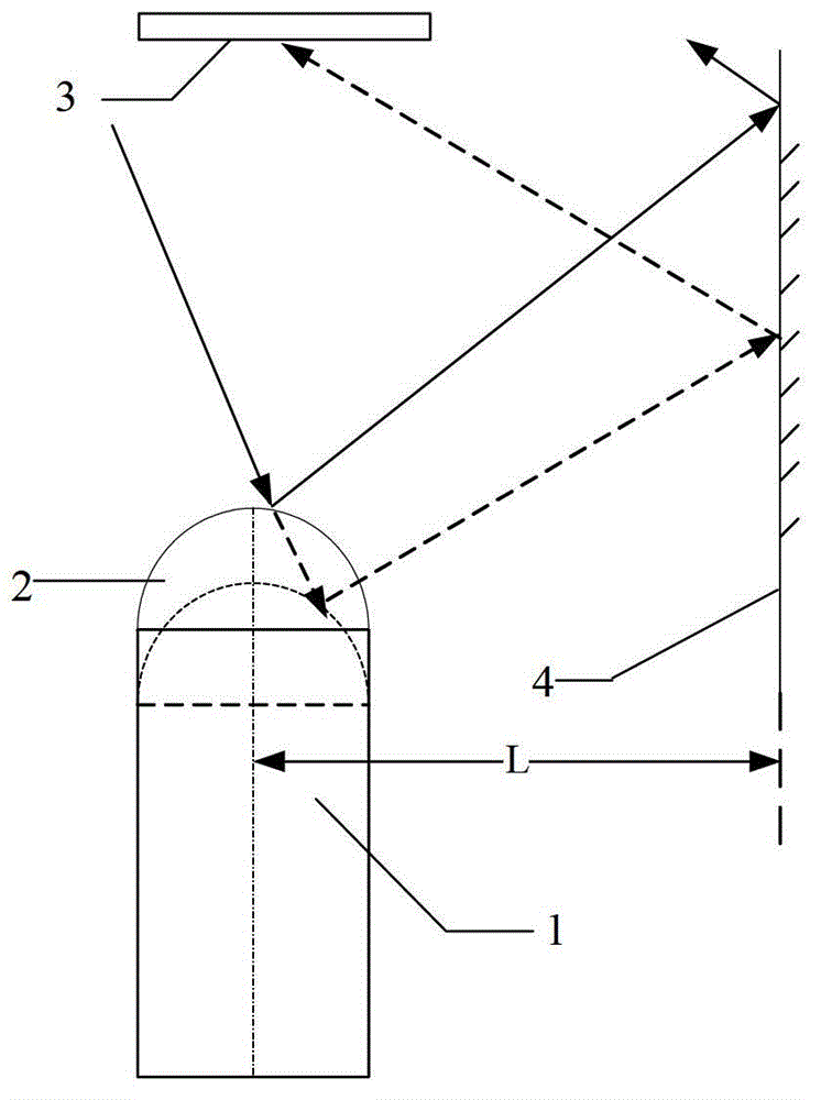
[0010] Specific implementation mode one: combine figure 1 Describe this embodiment, the device of magnetostrictive circuit breaker optical control described in this embodiment, it comprises the sensing head 1 of magnetostrictive material, sensing head spherical reflector 2, laser detector 3 and parallel reflector 4, The sensor head 1 of the magnetostrictive material is a cylinder, and the spherical reflector 2 of the sensor head is a hemisphere, and the sphere radius of the spherical reflector 2 of the sensor head is the same as that of the sensor head 1 of the magnetostrictive material. The radius of the end face circle is the same, the sensing head spherical reflector 2 is coaxially arranged with the sensing head 1 of the magnetostrictive material, and the bottom surface of the sensing head spherical reflector 2 is fixed on the bottom surface of the sensing head 1 of the magnetostrictive material. The upper end surface is connected with the sensor head 1 of the magnetostrictive
specific Embodiment approach 2
[0013] Specific embodiment two: the difference between this embodiment and the device for magnetostrictive circuit breaker optical control described in specific embodiment one is that it also includes a counter, the input end of the counter communicates with the electrical signal output end of the laser detector 3, The output terminal of the counter is the output terminal of the disconnection start signal of the device for magnetostrictive disconnection optical control.
[0014] Considering that there may be some non-faulty instantaneous currents that are too large during the operation of the power grid, the electrical signal output terminal of the laser detector 3 is connected to a counter, and a short-circuit signal is sent after N times of laser scanning times are detected, and N is an integer greater than 1; avoid Occurrence of malfunction.
specific Embodiment approach 3
[0015] Embodiment 3: This embodiment is a further limitation of the device for optical control of the magnetostrictive circuit breaker described in Embodiment 1. The sensor head 1 made of magnetostrictive material is realized by using a cylinder with a length of 200 mm.
PUM
| Property | Measurement | Unit |
|---|---|---|
| Length | aaaaa | aaaaa |
| Radius | aaaaa | aaaaa |
Abstract
Description
Claims
Application Information
 - R&D Engineer
- R&D Manager
- IP Professional
- Industry Leading Data Capabilities
- Powerful AI technology
- Patent DNA Extraction
Browse by: Latest US Patents, China's latest patents, Technical Efficacy Thesaurus, Application Domain, Technology Topic.
© 2024 PatSnap. All rights reserved.Legal|Privacy policy|Modern Slavery Act Transparency Statement|Sitemap