Light emitting diode drive system and display device using light emitting diode drive system

A technology of light-emitting diodes and driving systems, which can be used in three-dimensional systems, static indicators, instruments, etc., and can solve the problems of difficulty in selecting components of LED driving systems.

Inactive Publication Date: 2013-01-23
AMLINK SHANGHAI +1
View PDF4 Cites 5 Cited by
  • Summary
  • Abstract
  • Description
  • Claims
  • Application Information

AI Technical Summary

Problems solved by technology

That is to say, for the LED drive system, 2D mode and 3D mode are two different load characteristics, therefore, the requirements for t

Method used


Image

  • Light emitting diode drive system and display device using light emitting diode drive system
  • Light emitting diode drive system and display device using light emitting diode drive system
  • Light emitting diode drive system and display device using light emitting diode drive system

Examples


Embodiment Construction

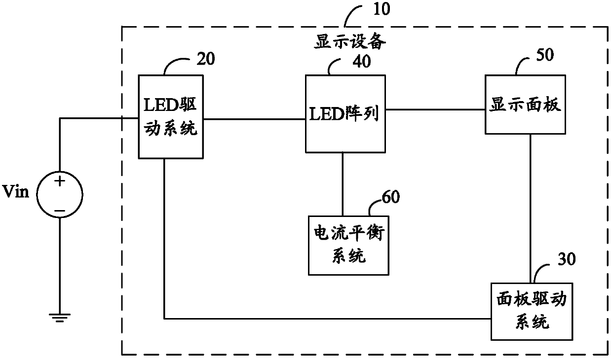
[0053] figure 1 It is a block diagram of the display device 10 in an embodiment of the present invention. The display device 10 includes an LED driving system 20 , a panel driving system 30 , a light emitting diode (Light Emitting Diode, LED) array 40 , a display panel 50 and a current balance system 60 . In this embodiment, the LED array 40 includes a plurality of LED strings connected in parallel, and each LED string is composed of a plurality of LEDs connected in series in the forward direction. The anode of the LED string refers to the anode of the first LED in the LED string, and the cathode of the LED array Refers to the cathode of the last LED in the LED string. The display device 10 has two display modes of two dimensions (2 dimensions, 2D) and three dimensions (3 dimensions, 3D), and for the LED driving system 20, the 2D mode and the 3D mode are two different load characteristics. The display panel 50 is used for 2D or 3D display. The panel drive system 30 is used to


PUM


Abstract

The invention relates to a light emitting diode drive system, comprising a microcontroller, a control circuit, a pulse width modulation controller, a first drive circuit, a second drive circuit, a first conversion circuit and a second conversion circuit. When a three-dimensional display is carried out on a display faceplate by the microcontroller, three-dimensional micro control signals are output. When the three-dimensional micro control signals are received by the control circuit, three-dimensional control signals are output. The second conversion circuit is connected with an external direct current voltage source, the control circuit and the second drive circuit; when the three-dimensional display is carried out on the display faceplate, according to the output of the second drive circuit, the external direct current voltage source is transformed to second direct current voltage so as to drive a light emitting diode array together with the first conversion circuit; and when a two-dimensional display is carried out on the display faceplate, the work stops. The invention also provides a display device. Under two-dimensional and three-dimensional modes, the light emitting diode drive system can change the output of the second drive circuit so as to meet the requirements of different loads and improve the elasticity selected by elements.

Description


Claims


Application Information

Patent Timeline
Owner AMLINK SHANGHAI
Why Eureka
Try Eureka