Novel high-chromium ferritic heat resistant steel and thermo-mechanical treatment process

A high-chromium ferrite, deformation heat treatment technology, applied in the field of high-chromium ferritic heat-resistant steel production, can solve the problems of high cost, complex production process, inability to guarantee corrosion resistance, etc., and achieves improved high temperature performance and thermal stability. Good performance and the effect of improving service temperature

Inactive Publication Date: 2013-03-27
TIANJIN UNIV
View PDF9 Cites 8 Cited by
  • Summary
  • Abstract
  • Description
  • Claims
  • Application Information

AI Technical Summary

Benefits of technology

This new method allows for better control over how well an alloy works when exposed to very hot environments like those used during manufacturing processes or welding operations. By creating tiny particles called magnesia (MgO) instead of solid iron), this improvement improves its resistance against strain failure under extreme conditions such as exposure to extremely high temperaturities without losing their effectiveness due to changes caused by these environmental factors.

Problems solved by technology

This patents describes various technical problem addressed in this patented paper relational science called iron/chromium alloys (FeCA), specifically referring to FeCxN+γ martensite type ferroelectric stainless steel used in industrial applications like gas turbine generators or electric utilities. These types of stains require strong wear resistances without sacrificially enhancing hardness and reducing ductility under extreme conditions. To address these issues, advanced techniques involving adding certain metallurgies and controlling processes may be applied. Additionally, there exist methods aiming towards better quality design and reduced costs through increased productivity and lower environmental concerns associated with energy consumption.

Method used


Image

  • Novel high-chromium ferritic heat resistant steel and thermo-mechanical treatment process
  • Novel high-chromium ferritic heat resistant steel and thermo-mechanical treatment process
  • Novel high-chromium ferritic heat resistant steel and thermo-mechanical treatment process

Examples


Embodiment 1

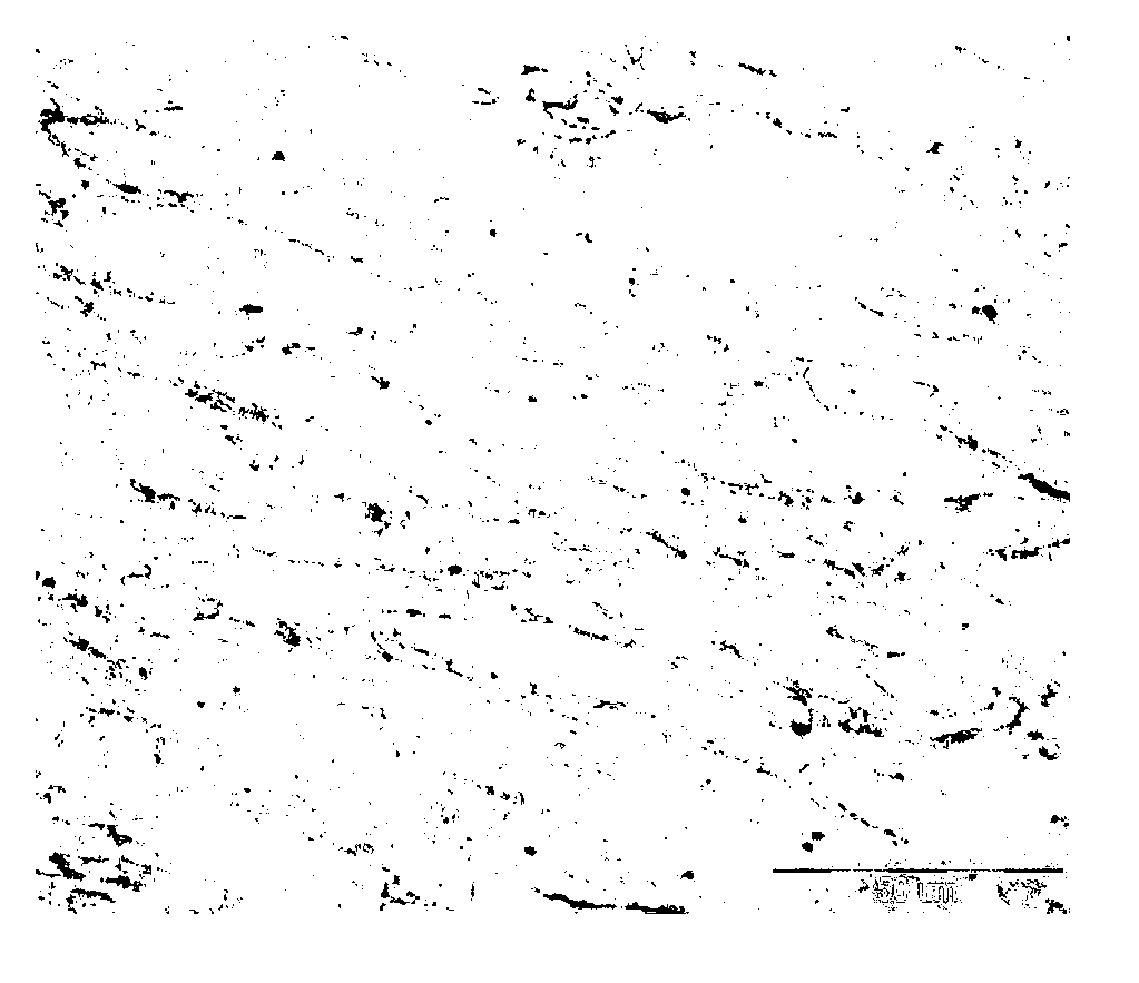
[0034] Example 1 The composition of high-chromium ferritic heat-resistant steel is shown in Table 1. The heat-resistant steel is processed into a cylindrical sample of Φ8×14mm, and the deformation heat treatment process experiment is carried out on the Gleeble1500D thermal simulation testing machine. The steps are: Heating at 5°C / s to 1100°C for 7 minutes to fully austenitize; then, cooling at -5°C / s to 850°C for 5s and then compressing and deforming, the deformation rate is 1 / s, and the deformation amount is 60% of time and space Cool to room temperature.

Embodiment 2

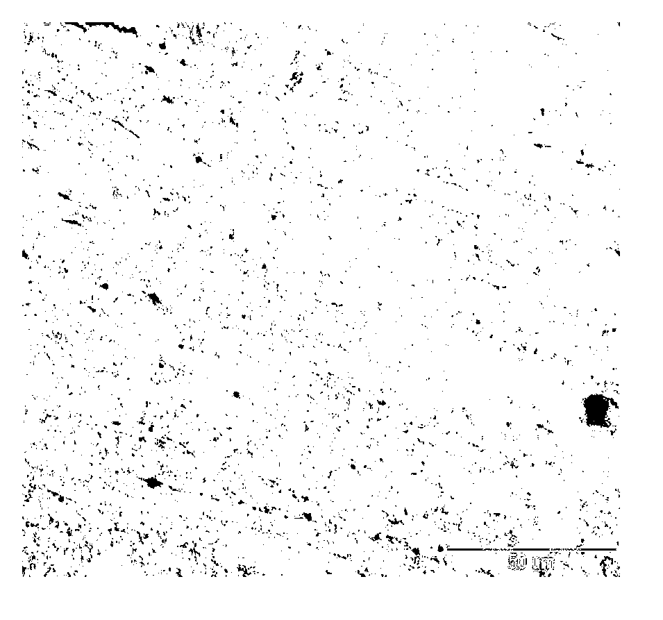
[0036] Example 2 The composition of high-chromium ferritic heat-resistant steel is shown in Table 1. The sample is processed into a cylinder of Φ8×14mm, and the deformation heat treatment process experiment is carried out on the Gleeble1500D thermal simulation testing machine. The steps are: s heat up to 1200°C for 5 minutes to fully austenitize, then cool to 800°C at 5°C / s and hold for 10s for 60% compression deformation at a deformation rate of 1 / s. After deformation, hold for 100s and then air cool to room temperature.

[0037] The sample after the above heat treatment was analyzed by OM morphology analysis and TEM morphology analysis. Figure 1(a) is the OM structure of Example 1, and Figure 1(b) is the OM structure of Example 2. It can be observed from Figure 1(a) that under this heat treatment process, the austenite grains cannot Dynamic recrystallization is carried out to obtain equiaxed grains without distortion, and the effect of deformation strengthening is improved;


PUM


Abstract

The invention discloses a novel high-chromium ferritic heat resistant steel, composed of the following components by mass percent: 0.08-0.1% of C, less than or equal to 0.5% of Si, 0.3-0.6% of Mn, 8.5-9.0% of Cr, 0.3-0.6% of Mo, 1.5-2.0% of W, 0.20-0.25% of V, 0.02% of Cu, 0.07-0.09% of Nb, less than 0.005% of Ti, 0.004-0.005% of B and less than 0.005% of N, and the balance of Fe and impurities. The thermo-mechanical treatment process of the steel comprises the following steps of: heating at the rate of 5 DEG C/s until the temperature reaches 1100-1200 DEG C and preserving heat for 5-10 min; and then cooling at the rate of 5 DEG C/s until the temperature reaches 900-700 DEG C, preserving heat for 5-10 s, performing compressive deformation at the deformation rate of 1/s by the deformation quantity of 50-70%; preserving heat for 0-100 s after the completion of deformation, and then performing air cooling until the temperature reaches the room temperature. The thermal treatment process provided by the invention is capable of promoting the precipitation of the MX phase having excellent stability, thereby improving the high temperature performance of the steel. Compared with the traditional thermal treatment process, the thermo-mechanical treatment process is simplified in process flow so that the production cost is reduced and the overall performance is improved; and therefore, the thermo-mechanical treatment process can be applied to actual production.

Description


Claims


Application Information

Patent Timeline
Owner TIANJIN UNIV
Why Eureka
Try Eureka