Pipeline gas leakage detecting device

A gas leak detection and detection device technology, applied in pipeline systems, gas/liquid distribution and storage, mechanical equipment, etc., can solve the problems of high labor and time consumption, low instrument detection efficiency, inconvenient movement, etc., to save time and manpower, easy to apply and promote, to provide the effect of work efficiency

Active Publication Date: 2013-04-24
NINGBO FATO AUTOMATION TECH
View PDF6 Cites 5 Cited by
  • Summary
  • Abstract
  • Description
  • Claims
  • Application Information

AI Technical Summary

Problems solved by technology

The current testing tool is a single detection instrument, and the detection gas pipelines can only come one by one. The detection efficiency of the instrument i

Method used


Image

  • Pipeline gas leakage detecting device

Examples


Embodiment

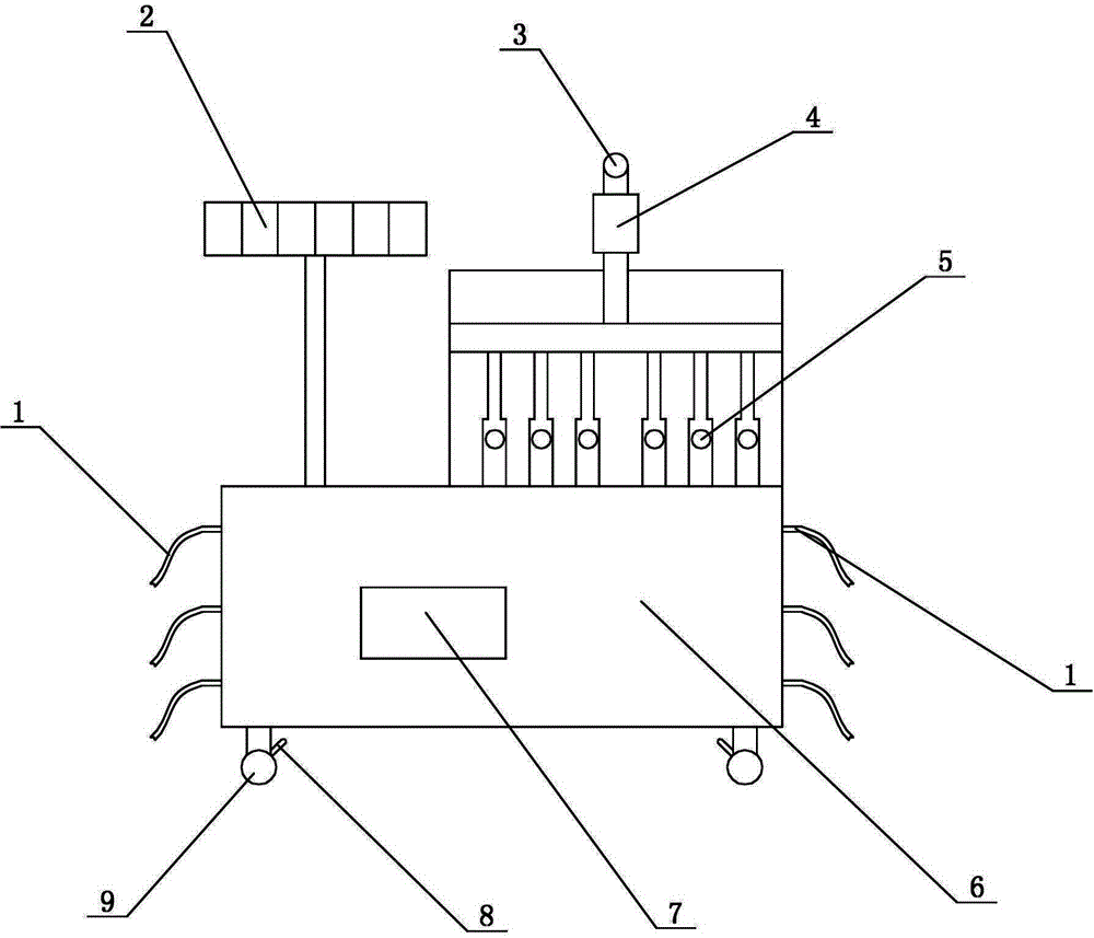
[0022] see figure 1 , a pipeline gas leakage detection device, including a casing 6, a controller 7 is arranged inside the casing 6, and the controller is electrically connected to a pressure detection device and an indicating device. The upper end of the housing 6 is provided with a bracket, and several pressure detection devices are installed in the bracket, and all the pressure detection devices are connected with an indicating device. The pressure detection device is connected with a pressure transmitter and a temperature transmitter arranged at the position to be detected.

[0023] In this embodiment, the pressure detection device includes a connecting pipe, and the connecting pipe communicates with the pressure gauge 5 provided in the bracket. The pressure gauge 5 corresponds to the connecting pipe one by one, and the pressure gauge 5 is electrically connected to the controller. Here, the pressure gauge is generally set inside the connecting pipe and does not leak out.


PUM


Abstract

The invention discloses a pipeline gas leakage detecting device which comprises an outer casing. A controller is arranged inside the casing, a support is arranged at the upper end of the casing, a plurality of pressure measurement devices are installed in the support, and all pressure measurement device are connected with an indicating device. The pressure measurement devices are arranged on a pressure transmitter and a temperature transmitter on a portion to be detected in a connecting mode, and the controller is electrically connected with the pressure measurement devices and the indicating device. Further, each pressure measurement device comprises a connecting tube which is arranged on a pressure gage in the support in a communicated mode, the pressure gage corresponds to the connecting tube one by one, and the pressure gage is electrically connected with the controller. A display device comprises a plurality of display screens which are electrically connected with the controller. The pipeline gas leakage detecting device can achieve simultaneous measurement on multiple channels, saves time and labor and provides work efficiency. The pipeline gas leakage detecting device is simple in structure, convenient to use, high in detection efficiency, and convenient to popularize and apply.

Description


Claims


Application Information

Patent Timeline
Owner NINGBO FATO AUTOMATION TECH
Why Eureka
Try Eureka