Convenient method for detecting abnormal waveform

A technology of abnormal waveform and detection method, applied in the field of electrical variable testing

Active Publication Date: 2013-07-17
RIGOL
View PDF6 Cites 6 Cited by
  • Summary
  • Abstract
  • Description
  • Claims
  • Application Information

AI Technical Summary

Problems solved by technology

The oscilloscope disclosed in this patent can record waveforms for a long time and play back the recorded waveform

Method used


Image

  • Convenient method for detecting abnormal waveform
  • Convenient method for detecting abnormal waveform
  • Convenient method for detecting abnormal waveform

Examples


Embodiment Construction

[0208] Preferred embodiments of the present invention will be described in detail below in conjunction with the accompanying drawings.

[0209] Referring to Fig. 6, it is a structural block diagram of the digital oscilloscope listed in this embodiment, the digital oscilloscope includes a storage unit 6011 for sequentially storing multi-frame measurement waveform data; an input unit 6012 for generating input control information; according to the input control information , acquire the abnormal waveform data, and display the abnormal waveform data in the waveform display unit 6013 in a waveform display mode.

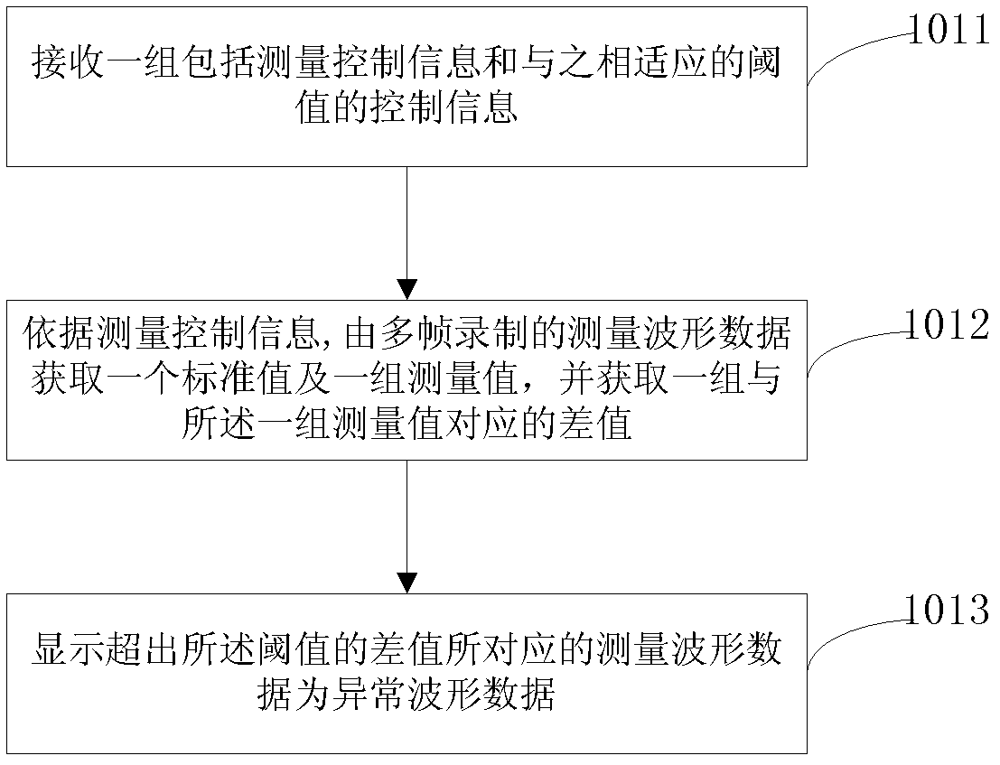
[0210] With reference to Fig. 1, the digital oscilloscope listed in this embodiment executes a detection step with a first abnormal waveform, including the following steps:

[0211] Step 1011: Receive a set of control information including measurement control information and a corresponding threshold;

[0212] Step 1012: Acquire a standard value and a set of measurement valu


PUM


Abstract

The invention provides a convenient method for detecting an abnormal waveform. The method is used for a digital oscilloscope and comprises the steps of receiving a group of control information containing measurement control information and a threshold matched with the measurement control information, obtaining a frame of standard waveform data and multiple frames of measurement waveform data from multi-frame recorded measurement waveform data according to the measurement control information, and according to the area between a waveform corresponding to each of the multiple frames of the measurement waveform data and a waveform corresponding to the standard waveform data, displaying the measurement waveform data which correspond to the area and exceed the threshold as abnormal waveform data. By the aid of the convenient method for detecting the abnormal waveform, detection of the abnormal waveform data can be conducted on the recorded measurement waveform data, the abnormal waveform data can be detected quickly and accurately through the area difference between the standard waveform data and the measurement waveform data, and differences between the measurement waveform data and the standard waveform data can be obtained, so that the abnormal waveform data can be analyzed conveniently.

Description


Claims


Application Information

Patent Timeline
Owner RIGOL
Why Eureka
Try Eureka