Signal transmitting method and signal receiving method based on TDCS (Transform Domain Communication System) differential transmission

A differential transmission and signal transmission technology, applied in the field of transform domain communication, can solve problems such as low communication security and waste of spectrum resources, and achieve the effect of improving security and frequency utilization

Inactive Publication Date: 2014-10-15
UNIV OF ELECTRONICS SCI & TECH OF CHINA
View PDF2 Cites 0 Cited by
  • Summary
  • Abstract
  • Description
  • Claims
  • Application Information

AI Technical Summary

Benefits of technology

This technology allows for efficient wireless communications by combining different types of signals into one signal that combines both spatial (coherence) and temporal dimensions. By doing this, it becomes more flexible than just transmitting binary data separately but still allowing them all together at once. It achieves these benefits through specific techniques such as quadrature phase shift keying or time division multiple access protocols.

Problems solved by technology

This patented technical solution described in the present describes a method called Time Division Multiplex Interference Technique (TMI)-based Digital Orthogonal Frequency Compression Technology (DTCC™) for efficiently reusing spectral resource during communications between different devices over multiple antennas simultaneously. Specifically, Dual Timing Interferometer Group (TTG IF)/Composite Delay Line Antenna Module (CDAM) converter converts analog signals into digital ones, followed by performing complex operations like convolution and interleaving onto these converted signals. These processes improve efficiency and reduce complexity compared to traditional methods such as coherence function techniques. Additionally, the proposed systems include various components including filters, mixers, quadrature circuits, CDMA modules, etc., resulting in improved reliability and network capacity capabilities. Overall, they aim to provide efficient and secure access to shared spectrals among mobile device networks.

Method used


Image

  • Signal transmitting method and signal receiving method based on TDCS (Transform Domain Communication System) differential transmission
  • Signal transmitting method and signal receiving method based on TDCS (Transform Domain Communication System) differential transmission
  • Signal transmitting method and signal receiving method based on TDCS (Transform Domain Communication System) differential transmission

Examples


Embodiment Construction

[0055] The technical solutions of the present invention will be described in detail below with reference to the accompanying drawings.

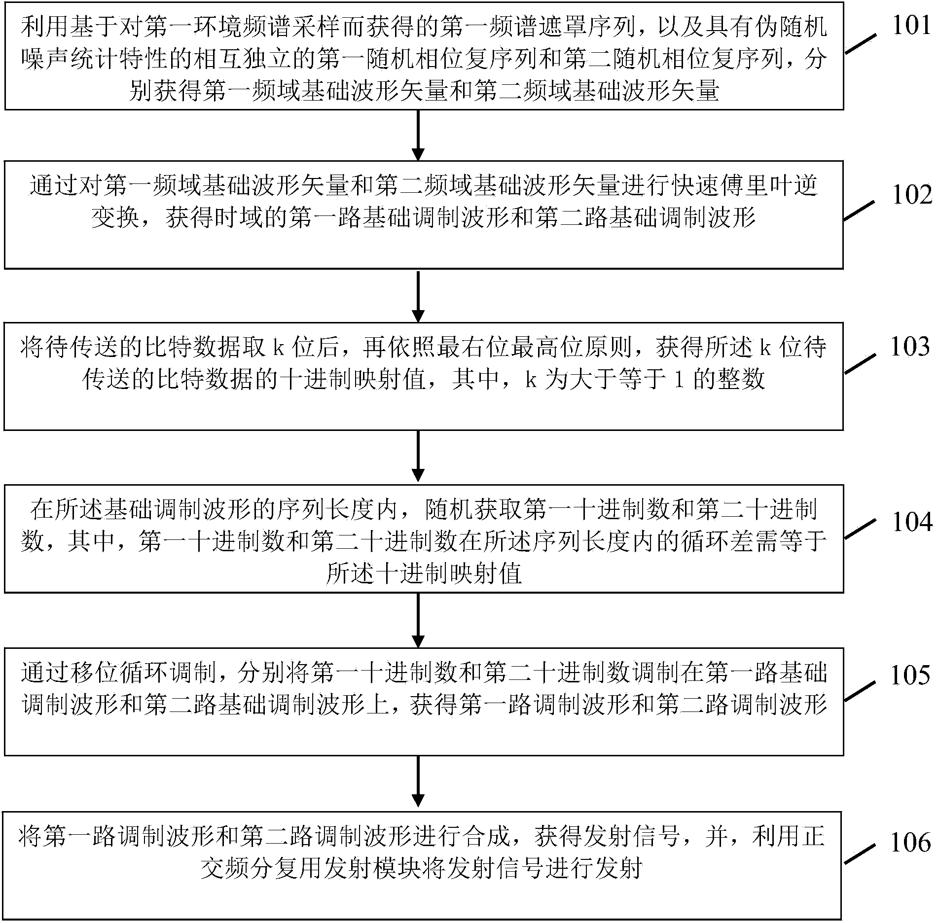
[0056] A signal transmission method based on differential transmission in a TDCS system is applied to the transmitting end of the system, and the method includes: using a first spectrum mask sequence obtained based on sampling a first environment spectrum, and a pseudo-random noise statistical characteristic. mutually independent first random phase complex sequence and second random phase complex sequence, respectively obtain the first frequency domain fundamental waveform vector and the second frequency domain fundamental waveform vector; by comparing the first frequency domain fundamental waveform vector and the second frequency domain fundamental waveform vector The waveform vector is subjected to inverse fast Fourier transform to obtain the first basic modulation waveform and the second basic modulation waveform in the time domain. The decim


PUM


Abstract

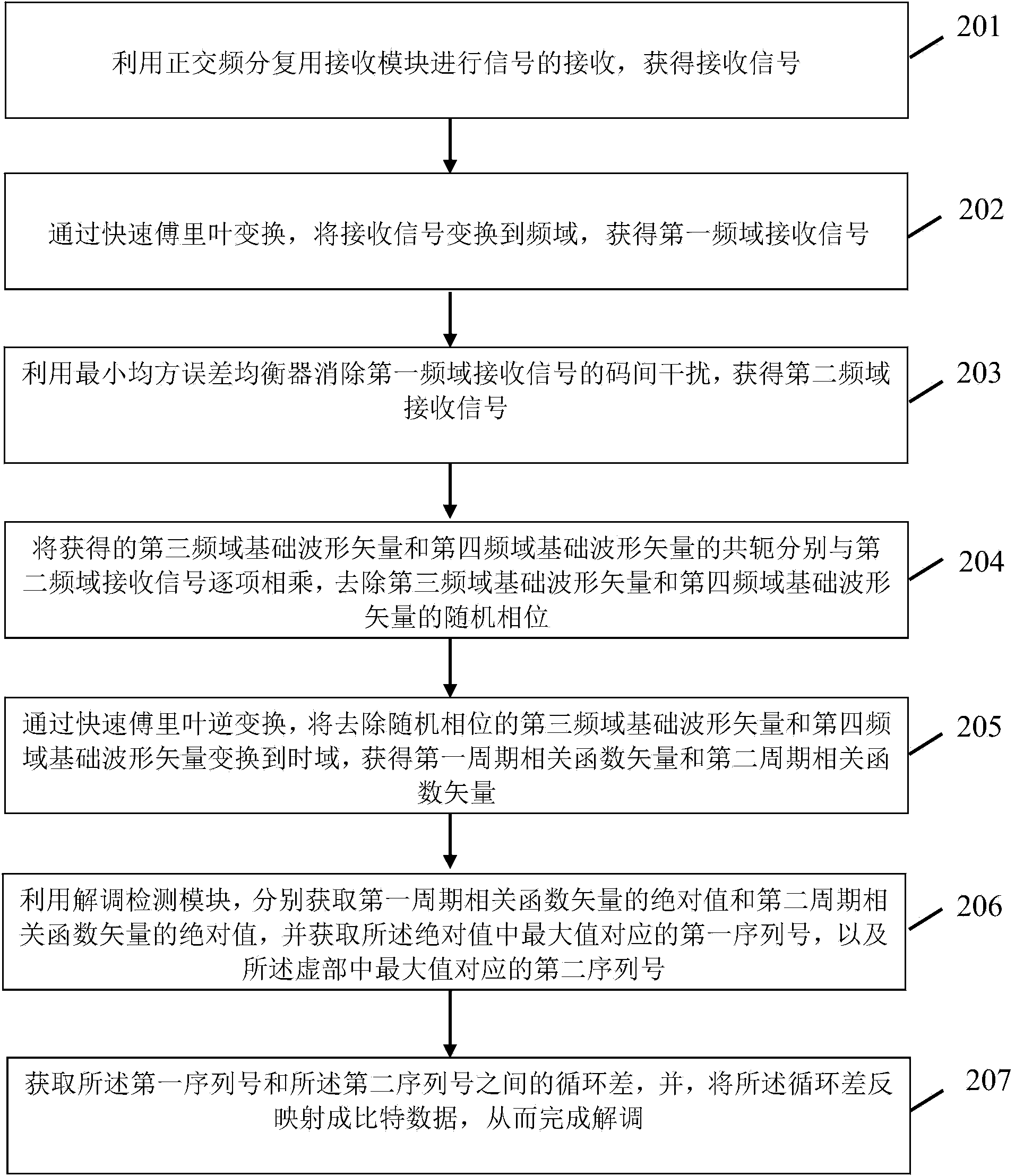
The invention provides a signal transmitting method and a signal receiving method based on TDCS (Transform Domain Communication System) differential transmission. The method comprises the following steps: acquiring a first frequency domain basic waveform vector and a second frequency domain basic waveform vector respectively by using a first frequency spectrum mask sequence as well as a first random phase complex sequence and a second random phase complex sequence which are independent of each other; performing inverse fast Fourier transform on the first frequency domain basic waveform vector and the second frequency domain basic waveform vector to obtain a first path basic modulation waveform and a second path basic modulation waveform of a time domain; extracting k bits of bit data to be transmitted, and acquiring the decimal system mapping value of the k bits of bit data to be transmitted according to a rightmost bit as highest bit principle; randomly acquiring a first decimal numeral and a second decimal numeral; acquiring a first path modulation waveform and a second path modulation waveform through shift circulation modulation; synthesizing the first path modulation waveform and the second path modulation waveform to obtain a transmission signal, and transmitting the transmission signal by using an orthogonal frequency-division multiplexing transmission module.

Description


Claims


Application Information

Patent Timeline
Owner UNIV OF ELECTRONICS SCI & TECH OF CHINA
Why Eureka
Try Eureka