Stainless branching screw

A technology of screw and wire separation, applied in the field of mechanical parts, can solve the problems of short service life and easy rust of screws, and achieve the effect of long service life and simple structure

Inactive Publication Date: 2013-07-24
黄亚军
View PDF0 Cites 1 Cited by
  • Summary
  • Abstract
  • Description
  • Claims
  • Application Information

AI Technical Summary

Benefits of technology

This patented wire splitter screw can be used for sealing up any holes or cracks that may occur during construction work without damaging it's materials. Its technical effect includes its easy manufacturing process with longer lifespan, resistance against rainwater damage, and ability to resist corrosion from other substances like salt spray when exposed to moisture conditions over time.

Problems solved by technology

This patented technical problem addressed in this patents relates to improving the durability and resistance against corrosion caused during use of regular tools such as screwdrivers or bolts due to their rotating movement along diagonal lines that can cause damage when they come into contact with other objects like metal plugs on electric wires or electronic components inside buildings.

Method used


Image

  • Stainless branching screw

Examples


Embodiment Construction

[0011] The preferred embodiments of the present invention will be described in detail below in conjunction with the accompanying drawings, so that the advantages and features of the present invention can be more easily understood by those skilled in the art, so as to define the protection scope of the present invention more clearly.

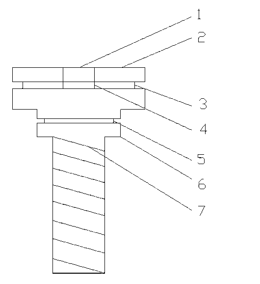
[0012] see figure 1 , a kind of anti-rust branching screw, comprising: a screw body 2, a first fixing groove 3, a second fixing groove 5, a screw rod 6, a thread 7 and a mounting hole 1, and the first fixing groove 3 is opened on the screw body 2, the second fixing groove 5 is opened at the rear end of the screw body 2, the screw rod 6 is integrally formed with the screw body 2 and is arranged on the top of the screw body 2, and the edge of the screw rod 6 is provided with threads 7. The tail end of the screw body 2 is provided with a mounting hole 1 .

[0013] In addition, the surface of the screw body 2, the thread 7 and the screw rod 6 are all s


PUM


Abstract

The invention discloses a stainless branching screw, which comprises a main screw body, a first fixing groove, a second fixing groove, a screw rod, threads and a mounting hole, wherein the first fixing groove is arranged at the front end of the main screw body, and the second fixing groove is arranged at the back end of the main screw body; the screw rod and the main screw body are integrated and are arranged at the top end of the main screw body, and the threads are arranged on the edge of the screw rod; and the mounting hole is formed at the tail end of the main screw body. Through the method, the stainless branching screw provided by the invention has the advantages of simple structure, long service life and waterproof and stainless performances.

Description


Claims


Application Information

Patent Timeline
Owner 黄亚军
Why Eureka
Try Eureka