Photographic device

A technology of camera device and camera optical system, which is applied in the field of camera device, can solve the problems such as the position deviation of the prism, and achieve the effect of firm fixing

Active Publication Date: 2013-08-21
OM DIGITAL SOLUTIONS CORP
View PDF6 Cites 14 Cited by
  • Summary
  • Abstract
  • Description
  • Claims
  • Application Information

AI Technical Summary

Benefits of technology

The technical effect that this patented technology solves by providing an improved way for fixing a special type of lens called Prism into an image capturing apparatus with its own camera's viewfinder window. This makes it easier to use these cameras while maintain their compact design.

Problems solved by technology

This patented technical problem addressed in this patents relates to improving the performance of cameras used in mobile devices while maintaining their thinner size without sacrificializing its functionality.

Method used


Image

  • Photographic device
  • Photographic device
  • Photographic device

Examples


Embodiment Construction

[0025] Next, preferred embodiments of the present invention will be described with reference to the drawings. In addition, in each of the drawings used in the following description, each constituent element is assumed to have a size that can be recognized on the drawing, so the scale is different for each constituent element, and the present invention is not limited to the size of the constituent elements described in these drawings. Quantity, shape of structural elements, ratio of size of structural elements and relative positional relationship of each structural element.

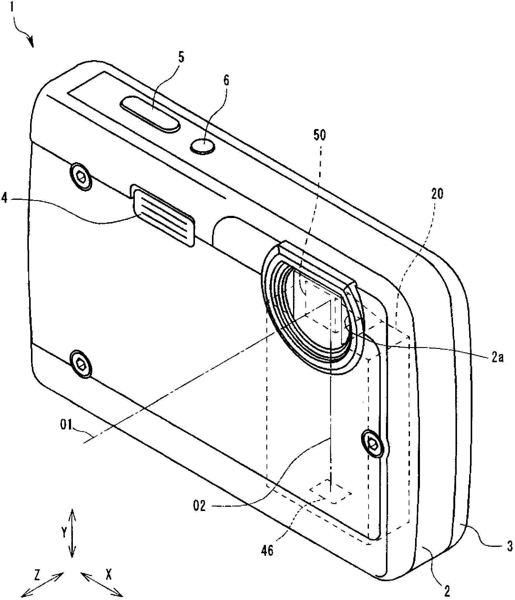
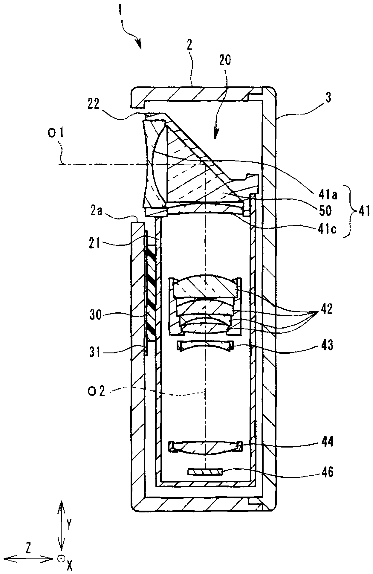
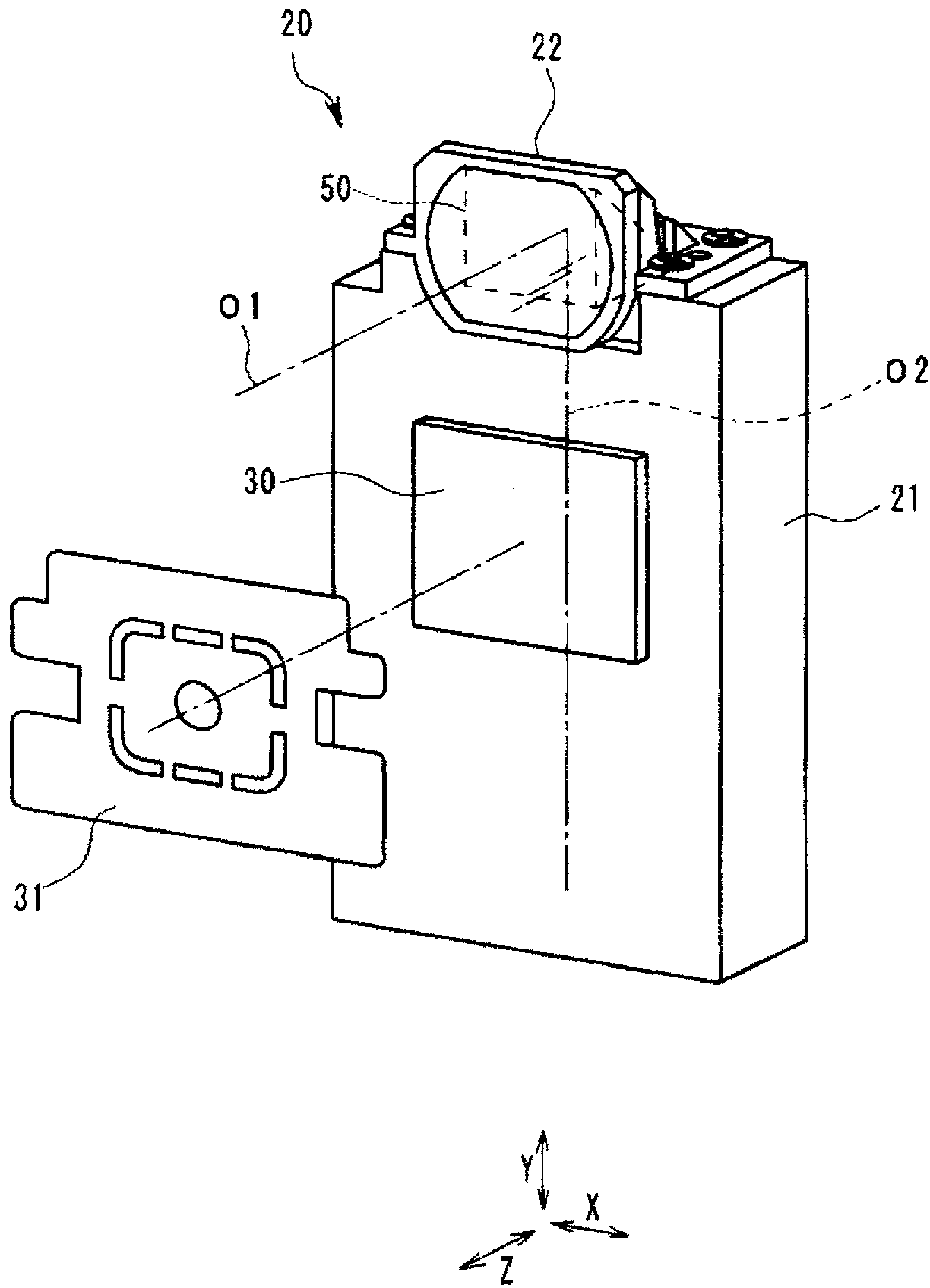
[0026] In this embodiment, the present invention is applied to an imaging device generally called an electronic camera, a digital camera, or the like. The imaging device 1 of the present embodiment is configured to have a lens frame 20 inside, and the lens frame 20 holds imaging optical system components such as lenses for forming a subject image and imaging optical system components arranged on the imaging p


PUM


Abstract

The invention provides a photographic device. In the photographic device comprising a photographic optical system component with a prism, the prism is fixed firmly so that the photographic device is not upsized. The photographic device comprises: a buffering part elastically supporting and retaining a lens frame of the photographic optical system component with the prism relative to a frame part; a prism retaining frame comprising a prism receiving chamber receiving the prism and forming a part of the lens frame; and an adhesive injection hole with one end being open at the outer surface of the lens retaining frame and the other end being open in the prism receiving chamber. The opening of the other end side of the adhesive injection hole is flat in shape and the length direction of the opening is the direction vertical to the direction where the buffering effect of the buffering part on the lens frame is weakest. The prism is fixed through adhesive injected from the adhesive injection hole.

Description


Claims


Application Information

Patent Timeline
Owner OM DIGITAL SOLUTIONS CORP
Why Eureka
Try Eureka