Atmospheric Plasma NC Machining Method of Freeform Surface Optical Parts
A technology of optical parts and plasma, which is applied in the field of plasma processing of large-diameter aspheric optical parts, to achieve the effect of avoiding surface residual stress and subsurface damage
- Summary
- Abstract
- Description
- Claims
- Application Information
AI Technical Summary
Benefits of technology
Problems solved by technology
Method used
Image

Examples
specific Embodiment approach 1
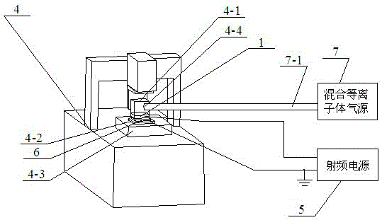
[0022] Specific implementation mode one: combine figure 1 As shown, its steps are:
[0023] Step 1: A large-diameter plasma torch 1 or a medium-diameter plasma torch 2 or a small-diameter plasma torch 3 or a large-diameter plasma torch 1 is installed on the insulating work frame 4-1 of the five-axis linkage machine tool 4 Or the plasma torch 2 of medium caliber or the plasma torch 3 of small caliber can be connected with the output end of radio frequency power supply 5 as the anode of atmospheric plasma discharge;
[0024] Step 2: Fix the optical part 6 to be processed on the ground electrode 4-2, and the ground electrode 4-2 is fixed on the horizontal movement workbench 4-3 of the five-axis linkage machine tool 4; ground the ground electrode 4-2 as the atmosphere The negative electrode of plasma discharge; When the large-diameter plasma torch 1 is installed on the insulating work frame 4-1, the air inlet port 1-1 of the large-caliber plasma torch 1 can pass through the guide on
specific Embodiment approach 2
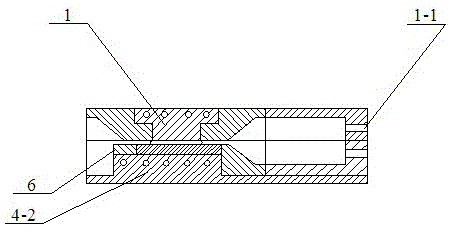
[0035] Specific implementation mode two: combination figure 2 Explain that the difference between this embodiment and the specific embodiment one is that the discharge working surface of the large-diameter plasma torch 1 is a square plane or a circular plane, and its material is aluminum, and it is connected with the output end of the radio frequency power supply 5 as a The anode of the atmospheric plasma discharge is provided with an air inlet 1-1 at its side position, and the air inlet 1-1 is connected with the air outlet of the air guide hole 4-4 on the insulating work frame 4-1; when the large diameter When the plasma torch 1 is used for atmospheric plasma processing, the flow rate of the plasma gas is 2L / min-5L / min, the gas flow rate of the reaction gas is 20ml / min-90ml / min, and the ratio of the flow rate of the auxiliary gas to the reaction gas is 0 %-50%, the added RF power range is 200W-400W. Other method steps are the same as those in the first embodiment.
specific Embodiment approach 3
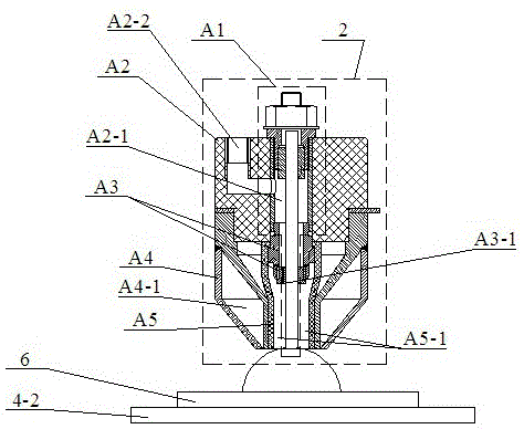
[0036] Specific implementation mode three: combination image 3 Explain that the difference between this embodiment and the first embodiment is that the plasma torch 2 with a medium diameter is composed of an inner electrode A1, a circular polytetrafluoroethylene connection block A2, a circular insulating fixing sleeve A3, a hollow circular ring Consists of external electrode A4 and circular tube ceramic nozzle A5;
[0037] The upper end surface of the circular polytetrafluoroethylene connecting block A2 is provided with an air inlet A2-2 connected with the inner hole A2-1 of the circular polytetrafluoroethylene connecting block A2, and the circular insulating fixing sleeve A3 is provided with There are a plurality of ventilation holes A3-1, and a cooling cavity A4-1 is provided inside the hollow circular outer electrode A4; the upper end of the inner electrode A1 is embedded in the inner hole A2-1 of the circular PTFE connection block A2 In the upper end, the ring-shaped insula
PUM
 Abstract
Description
Claims
Application Information
 - R&D Engineer
- R&D Manager
- IP Professional
- Industry Leading Data Capabilities
- Powerful AI technology
- Patent DNA Extraction
Browse by: Latest US Patents, China's latest patents, Technical Efficacy Thesaurus, Application Domain, Technology Topic.
© 2024 PatSnap. All rights reserved.Legal|Privacy policy|Modern Slavery Act Transparency Statement|Sitemap