Infrared focal plane array and enabling control circuit of reading circuit of infrared focal plane array

An infrared focal plane and control circuit technology, applied in the field of infrared focal plane array, can solve the problems of small leakage current, not system power consumption, etc., and achieve the effect of preventing excessive power consumption and controlling power consumption

Active Publication Date: 2013-11-27
UNIV OF ELECTRONICS SCI & TECH OF CHINA
View PDF4 Cites 5 Cited by
  • Summary
  • Abstract
  • Description
  • Claims
  • Application Information

AI Technical Summary

Benefits of technology

This technology allows for better energy management during AC adapter operation based on factors like voltage levels or battery usage level. It uses multiple signals from these sources together to accurately adjust how much electricity goes into each device's components when they turn off without overloading them with extra electrical charge that could be harmful if left unattended. Additionally, this system includes features such as monitoring input voltages and determining their peak value, allowing users to monitor the amount of time it takes before turning back up again. Overall, this innovation helps reduce unnecessary use of resources while still providing precise performance benefits.

Problems solved by technology

This patents describes how reducing energy usage can help reduce heat generation during operation while maintaining performance. However, this requires precise monitoring of certain parameters such as thermal sensitivity materials used in detectors.

Method used


Image

  • Infrared focal plane array and enabling control circuit of reading circuit of infrared focal plane array
  • Infrared focal plane array and enabling control circuit of reading circuit of infrared focal plane array
  • Infrared focal plane array and enabling control circuit of reading circuit of infrared focal plane array

Examples


Embodiment Construction

[0021] The enabling control circuit of the infrared focal plane array readout circuit and the infrared focal plane array thereof according to the embodiments of the present invention will be described in detail below with reference to the accompanying drawings.

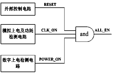
[0022] Such as figure 1 As shown, in one embodiment of the present invention, an enabling control circuit of an infrared focal plane array readout circuit includes an AND gate, an external control circuit, an analog power-on and power consumption detection circuit, and a digital power-on detection circuit.

[0023] The AND gate includes a first input terminal, a second input terminal, a third input terminal and an output terminal.

[0024] The external control circuit is used to generate a reset signal RESET, and its output terminal is connected to the first input terminal of the AND gate.

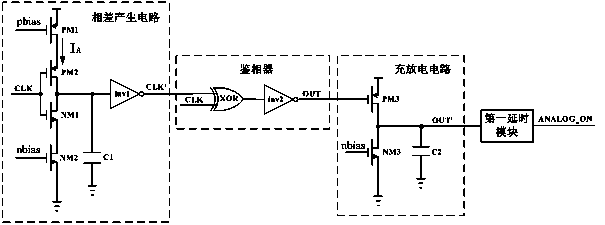
[0025] The analog power-on and power consumption detection circuit is used to generate an analog power-on and power consumption de


PUM


Abstract

The embodiment of the invention discloses an enabling control circuit of a reading circuit of an infrared focal plane array. The enabling control circuit comprises an and gate, an external control circuit, a simulation power-on and power consumption detection circuit, and a digital power-on detection circuit. The external control circuit, the simulation power-on and power consumption detection circuit and the digital power-on detection circuit are connected to three input ends of the and gate respectively, and the output end of the and gate outputs an enabling control signal. According to the enabling control circuit, the enabling control signal is jointly controlled through an external control signal, a digital power-on detection signal and a simulation power-on and power consumption detection signal, the simulation power-on and power consumption detection signal is added to an enabling control module, thus whether a simulation module is powered on or not can be detected, the situation of overhigh power consumption can be prevented on the whole, and power consumption is effectively controlled.

Description


Claims


Application Information

Patent Timeline
Owner UNIV OF ELECTRONICS SCI & TECH OF CHINA
Why Eureka
Try Eureka