Self-locking pressure signal feedback device

A pressure signal and feedback device technology, used in fire rescue and other directions, can solve the problems of no self-locking function, unable to confirm the fire extinguishing agent in the protection area in time, and achieve the effect of compact structure, convenient and fast installation, and safe and reliable operation.

Active Publication Date: 2014-01-22
浙江信达可恩消防实业有限责任公司
View PDF12 Cites 9 Cited by
  • Summary
  • Abstract
  • Description
  • Claims
  • Application Information

AI Technical Summary

Benefits of technology

The technical effect that this new design solves are its small size, easy installation, safety, reliability, ease of use without requiring an external power source or starting up again from time to start with.

Problems solved by technology

This patented describes an automated fire fighting system with a sensor called a pressure signal feedback device (PTL) for monitoring when there may still remain some flammable material inside it during fires or other emergencies such as power failures. However, this problem cannot be solved by simply relying on PTL signals alone without being able to verify if any protective areas were covered up due to uncontrolled inflammatory responses caused by these events.

Method used


Image

  • Self-locking pressure signal feedback device

Examples


Embodiment Construction

[0016] In order to enable those skilled in the art to better understand the solutions of the present invention, the technical solutions in the embodiments of the present invention will be described clearly and completely in conjunction with the accompanying drawings in the embodiments of the present invention.

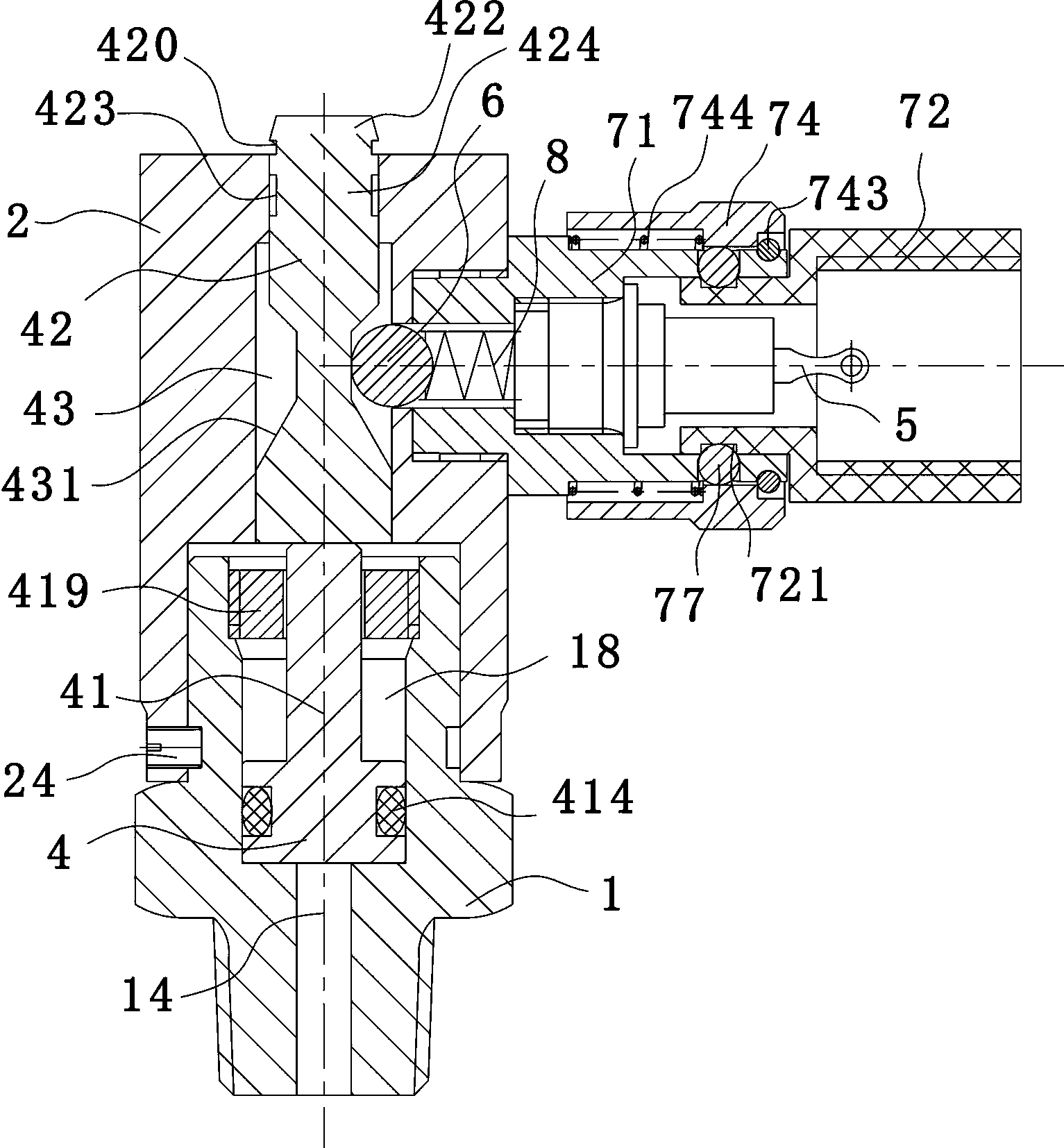
[0017] Such as figure 1 As shown, a self-locking pressure signal feedback device includes a valve body 1, a valve cover 2, a piston 4 and a micro switch 5. The valve cover 2 is covered outside the upper end of the valve body. Specifically, the valve body and the valve The caps are rotatably connected, that is, the valve cap can be rotated 360 degrees to facilitate the adjustment of the outlet direction as required. The valve cap is provided with a limit screw 24 that can limit its tripping; the piston 4 is located in the valve body 1, the valve body 1 is provided with a channel 14 for gas circulation and a chamber 18 for the piston 4 to move up and down. The chamber 18 and t


PUM


Abstract

The invention discloses a self-locking pressure signal feedback device which comprises a valve body, a valve cover, a piston, a microswitch and a channel, wherein the piston is provided with a lower piston body and an upper piston body; the valve body is internally provided with a baffle part defining the moving range of the lower piston body; the top of the upper piston body is provided with an exposed section protruding out of the valve cover; a wide-mouth groove internally provided with a ball is formed in the side part of the upper piston body, is perpendicular to the moving direction of the upper piston body and is provided an inclined wall facilitating vertical rolling of the ball; one side of the ball is arranged in the wide-mouth groove, and one side, outside the wide-mouth groove, of the ball is connected with the microswitch through an elastic part; the ball is pushed out of the wide-mouth groove by the upper piston body and outwards extrudes the elastic part when the piston is located at the topmost part; the ball moves into the wide-mouth groove under the counter force of the elastic part when the piston is located at the bottommost part. The device is compact in integral structure and convenient and rapid to install, has a self-locking function, can be reset only by man power after being started and is safe and reliable in operation, and system debugging does not need air pressure starting and can be carried out manually.

Description


Claims


Application Information

Patent Timeline
Owner 浙江信达可恩消防实业有限责任公司
Why Eureka
Try Eureka