Data transmission system and data transmission method
A data transmission system and data packet technology, applied in the field of geophysical exploration, can solve the problem of data transmission rate reduction and achieve the effect of improving transmission efficiency
- Summary
- Abstract
- Description
- Claims
- Application Information
AI Technical Summary
Benefits of technology
Problems solved by technology
Method used
Image

Examples
Embodiment 1
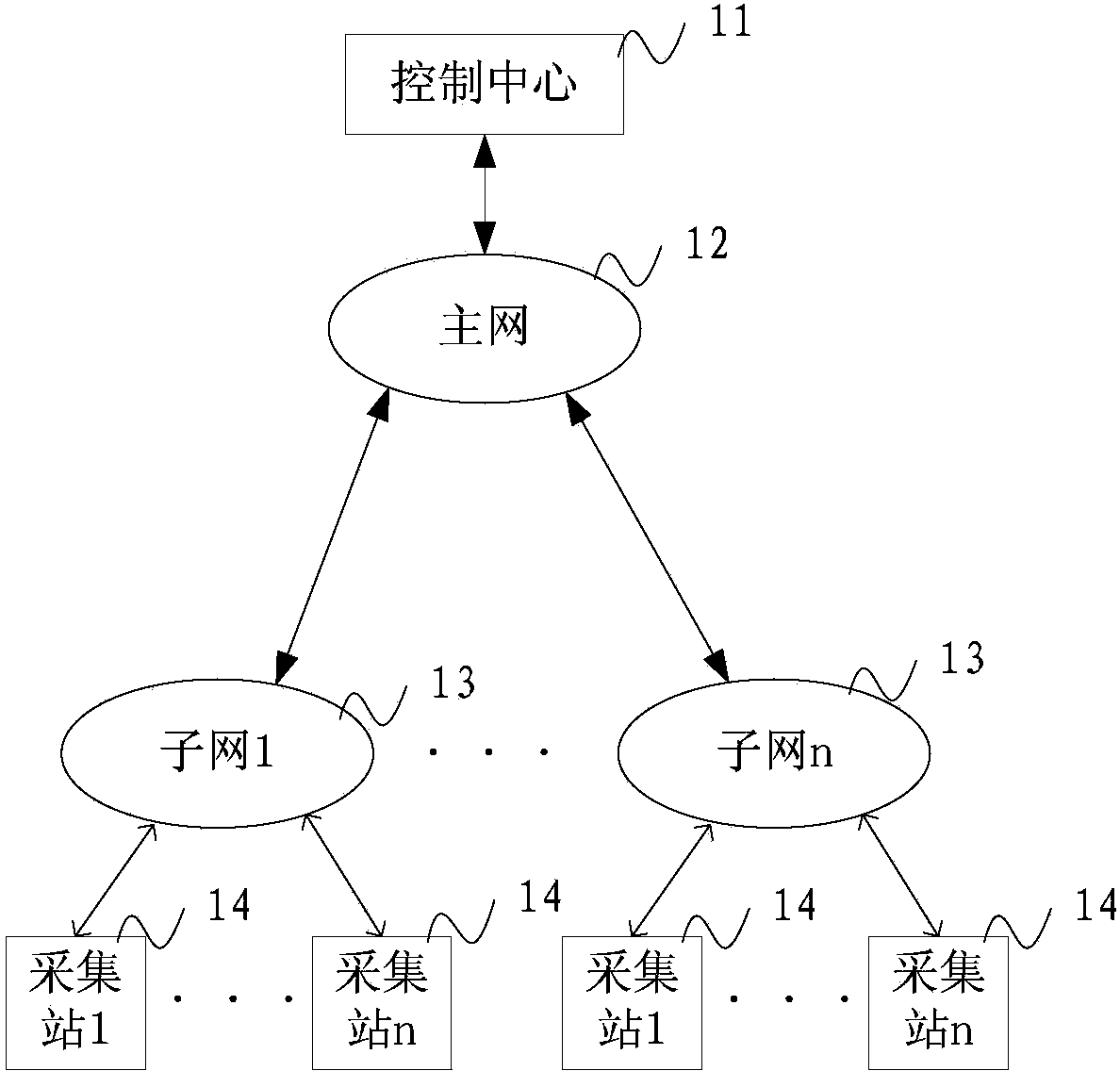
[0044] Such as figure 1 As shown, the present embodiment provides a data transmission system, including: a control center 11, the control center 11 is connected to at least one subnet 13 through the main network 12, and each subnet 13 is connected to at least one data collection device 14;
[0045] The data collection device 14 is arranged in the field for collecting data information; the subnet 13 is used for obtaining the data information collected by the data collection device 14 and sending it to the control center 11 through the main network 12 A data packet containing the data information.
[0046] In this embodiment, the control center 11 may be a computer device, etc., and the data collection device 14 may collect other data besides data information.
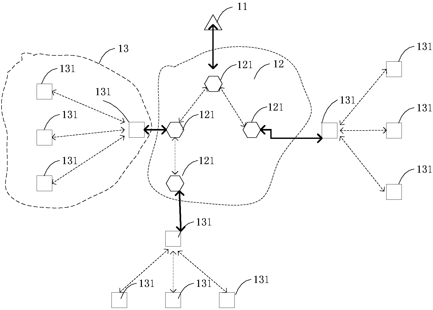
[0047] figure 2 An example network diagram provided for this embodiment, such as figure 2 As shown, the main network 12 includes at least one main network node 121 , and the subnet 13 includes at least one subnet node
Embodiment 2
[0059] Such as Figure 4 As shown, this embodiment provides a data transmission method, which can be performed by figure 1 Executed in subnet 13, the method includes:
[0060] 41. The subnet acquires data information collected by at least one data collection device deployed in the field.
[0061] 42. The subnet sends the data packet to the control center through the main network.
[0062] In this embodiment, optionally, the data information collected by the data collection device is electromagnetic data; or, the data information is device status information; or, the data information is the processing of the collected electromagnetic data by the data processing device. process the information received. Wherein, the device state information includes at least one of the following: battery voltage, GPS information of a global positioning system, and grounding resistance.
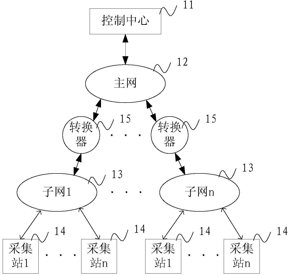
[0063] In this embodiment, optionally, the subnet is connected to the main network through a converter, and
Embodiment 3
[0077] In this embodiment, the data information collected by the data collection device is electromagnetic data; or, the data information is device status information; or, the data information is information obtained by processing the collected electromagnetic data by the data processing device . Wherein, the device state information includes at least one of the following: battery voltage, GPS information of a global positioning system, and grounding resistance.
[0078] A data sending method provided in this embodiment, the method can be executed by the control center in the above embodiment, such as Figure 7a As shown, the method includes:
[0079] 71. Obtain a user's control instruction for the data collection device.
[0080] Specifically, the control center obtains the operator's control instructions for the data collection equipment.
[0081] 72. Generate a control code according to the control instruction.
[0082] Specifically, a control code that can be recognized b
PUM
 Abstract
Description
Claims
Application Information
 - R&D Engineer
- R&D Manager
- IP Professional
- Industry Leading Data Capabilities
- Powerful AI technology
- Patent DNA Extraction
Browse by: Latest US Patents, China's latest patents, Technical Efficacy Thesaurus, Application Domain, Technology Topic.
© 2024 PatSnap. All rights reserved.Legal|Privacy policy|Modern Slavery Act Transparency Statement|Sitemap