Building water overflow automatic alarm control system
A technology of automatic alarm and control system, applied in the direction of electrical program control, comprehensive factory control, etc., to avoid property loss, economical and practical, and simple results
- Summary
- Abstract
- Description
- Claims
- Application Information
AI Technical Summary
Benefits of technology
Problems solved by technology
Method used
Image

Examples
specific Embodiment approach 1
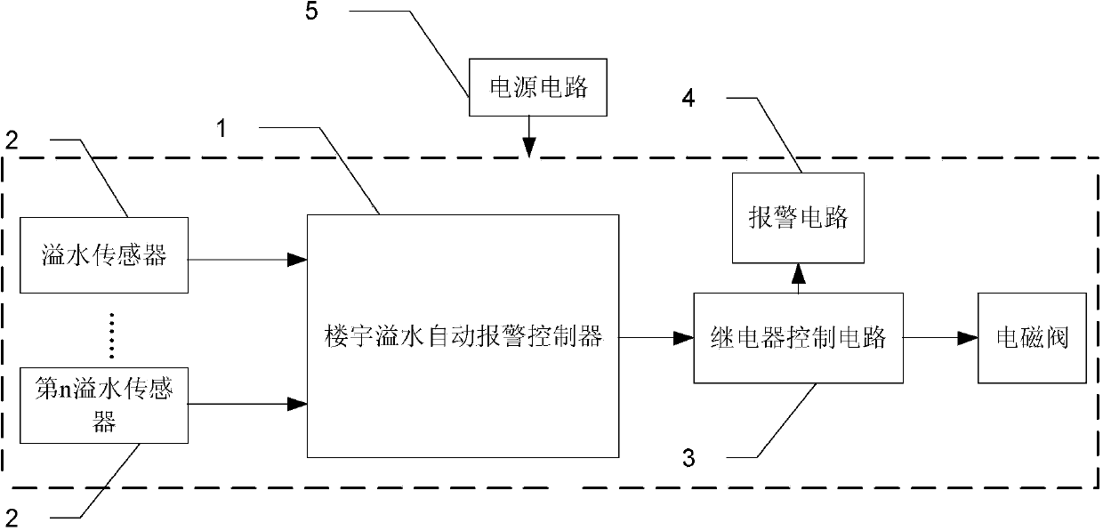
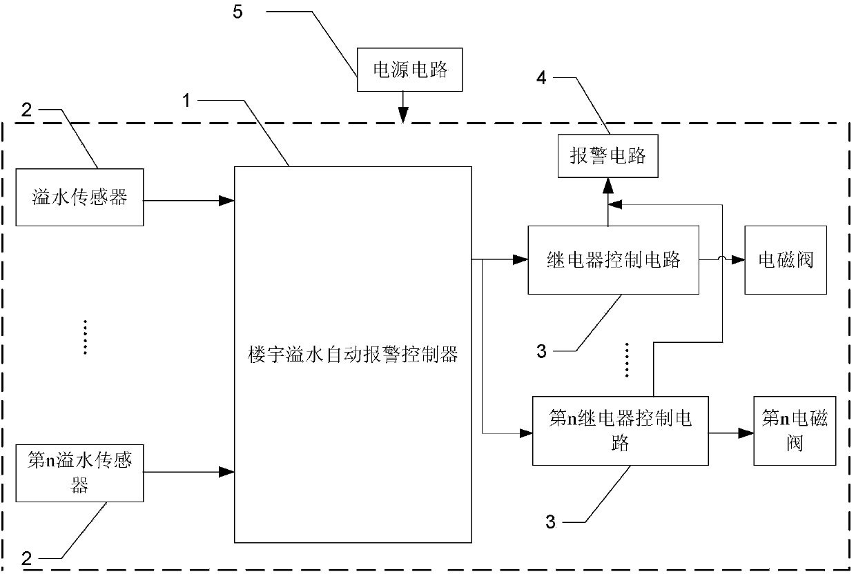
[0026] Specific implementation mode one: combine figure 1 and figure 2 Describe this embodiment, the building water overflow automatic alarm control system described in this embodiment, it includes a building water overflow automatic alarm controller 1, one or more overflow sensors 2, a relay control circuit 3, an alarm circuit 4 and a power supply circuit 5;
[0027] The building overflow automatic alarm controller 1 includes one or more hysteresis voltage comparison circuits,
[0028] The detection signal output end of each overflow sensor 2 is connected with the detection signal input end of a hysteresis voltage comparison circuit, and the detection signal output end of the hysteresis voltage comparison circuit is connected with the detection signal input end of the relay control circuit 3, and the relay control circuit 3 passes through the relay To control the opening or closing of the electromagnetic valve in the water supply pipeline in the building, the control signal ou
specific Embodiment approach 2
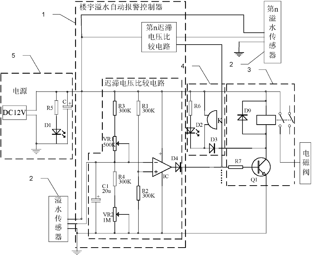
[0046] Embodiment 2: This embodiment is a further limitation of the building water overflow automatic alarm control system described in Embodiment 1. The relay control circuit 3 includes a resistor R7, a diode D9, an NPN transistor Q1 and a relay;
[0047] The cathode of the diode D9, one end of the coil of the relay and one end of a switch of the relay are simultaneously connected to the positive pole of the power supply circuit 5;
[0048] The cathode of the diode D4 is connected to one end of the resistor R7, the other end of the resistor R7 is connected to the base of the NPN transistor Q1, and the collector of the NPN transistor Q1 is connected to the anode of the diode D9 and the other end of the coil of the relay simultaneously.
[0049] The other end of a switch of the relay is connected to the opening or closing of the solenoid valve to be controlled in the building.
specific Embodiment approach 3
[0050] Specific embodiment 3: This embodiment is a further limitation of the building water overflow automatic alarm control system described in specific embodiment 2. The alarm circuit 4 includes a diode D3, a buzzer K, a resistor R6 and a light-emitting diode D2;
[0051] One end of the resistor R6 and one end of the buzzer K are connected to the positive pole of the power supply circuit 5 at the same time,
[0052] The other end of the resistor R6 is connected to the anode of the light-emitting diode D2, the cathode of the light-emitting diode D2 is connected to the other end of the buzzer K and the anode of the diode D3, and the cathode of the diode D3 is connected to the other end of the coil of the relay.
PUM
 Abstract
Description
Claims
Application Information
 - R&D Engineer
- R&D Manager
- IP Professional
- Industry Leading Data Capabilities
- Powerful AI technology
- Patent DNA Extraction
Browse by: Latest US Patents, China's latest patents, Technical Efficacy Thesaurus, Application Domain, Technology Topic.
© 2024 PatSnap. All rights reserved.Legal|Privacy policy|Modern Slavery Act Transparency Statement|Sitemap