Amplifier circuit

An amplifier circuit and operational amplifier technology, applied in high-frequency amplifiers, electrical components, transmission systems, etc., can solve the problem that the output OIP3 is difficult to reach a high level, and achieve the effect of improving performance

Inactive Publication Date: 2014-05-07
CHINA ELECTRONICS TECH GRP CORP NO 14 RES INST
View PDF4 Cites 2 Cited by
  • Summary
  • Abstract
  • Description
  • Claims
  • Application Information

AI Technical Summary

Problems solved by technology

[0007] Due to the distortion current i m1 and i m2 The existe

Method used


Image

  • Amplifier circuit
  • Amplifier circuit
  • Amplifier circuit

Examples


Embodiment Construction

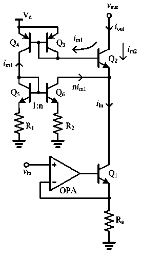
[0017] The technical solutions of the present invention will be described in detail below in conjunction with the accompanying drawings.

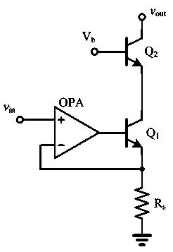
[0018] Such as image 3 The circuit diagram of the present invention shown, a kind of amplifier circuit, comprises input transconductance circuit and output circuit, and described input transconductance circuit comprises operational amplifier OPA, emitter resistance R S and the first transistor Q 1 , the inverting terminal of the operational amplifier OPA is connected to the first transistor Q 1 emitter, the first transistor Q 1 The emitter via the emitter resistor R S After grounding, the first triode Q 1 The base of the operational amplifier OPA is connected to the output terminal, and the non-inverting terminal of the operational amplifier OPA is used as the input terminal of the amplifier circuit, and the output circuit includes a second triode Q 2 , the second transistor Q 2 The emitter is connected to the first transistor Q 1 coll


PUM


Abstract

The invention discloses an amplifier circuit which comprises an input transconductance circuit, an output circuit and a distortion offset feedback loop, wherein the distortion offset feedback loop comprises a third triode, a fourth triode, a fifth triode, a sixth triode, a first resistor and a second resistor, wherein a base electrode of the third triode is connected with that of the fourth triode; an emitting electrode of the third triode is connected with that of the fourth triode; the emitting electrode of the fourth electrode is connected with a bias voltage; a base electrode of the second triode is respectively connected with a collecting electrode of the second triode and a base electrode of the third triode; a base electrode of the fifth triode is connected with that of the six triode; the collecting electrode of the fifth triode is respectively connected with a base plate of the fifth triode and a collecting electrode of the fourth triode; an emitting electrode of the fifth triode is grounded by virtue of the first resistor; a collecting electrode of the six triode is connected to the emitting electrode of the second triode; an emitting electrode of the sixth triode is grounded by virtue of the second resistor. According to the amplifier circuit, a distortion offset technology is adopted, so that the OIP3 output performance is improved.

Description


Claims


Application Information

Patent Timeline
Owner CHINA ELECTRONICS TECH GRP CORP NO 14 RES INST
Why Eureka
Try Eureka