Passive mixer having transconductance amplifier with source degeneration capacitance

Active Publication Date: 2009-04-02
AVAGO TECH INT SALES PTE LTD
View PDF4 Cites 5 Cited by
  • Summary
  • Abstract
  • Description
  • Claims
  • Application Information

AI Technical Summary

Problems solved by technology

Further, the calibration circuit 102 was needed to detect the mixer gain variation, and then to tune the capacitor banks, resulting in significant power consumption.

Method used


Image

  • Passive mixer having transconductance amplifier with source degeneration capacitance
  • Passive mixer having transconductance amplifier with source degeneration capacitance
  • Passive mixer having transconductance amplifier with source degeneration capacitance

Examples


Embodiment Construction

[0025]This description of the exemplary embodiments is intended to be read in connection with the accompanying drawings, which are to be considered part of the entire written description.

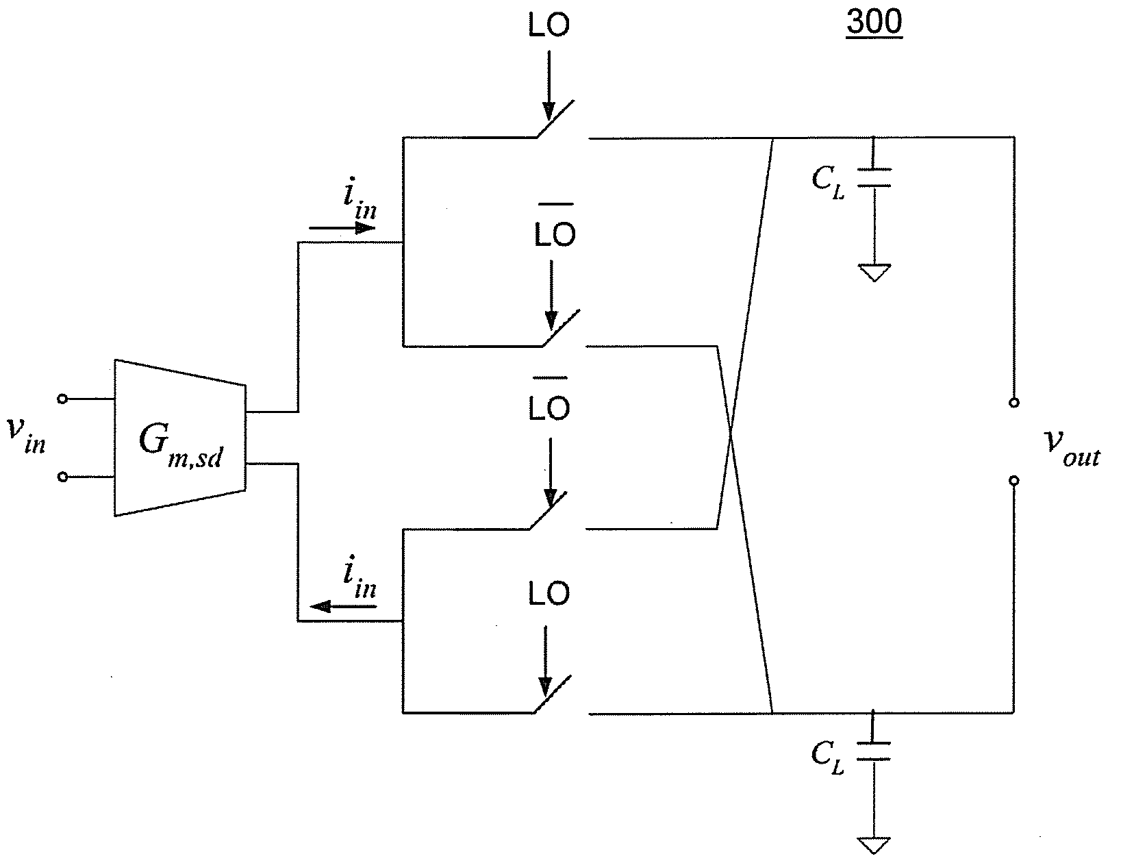
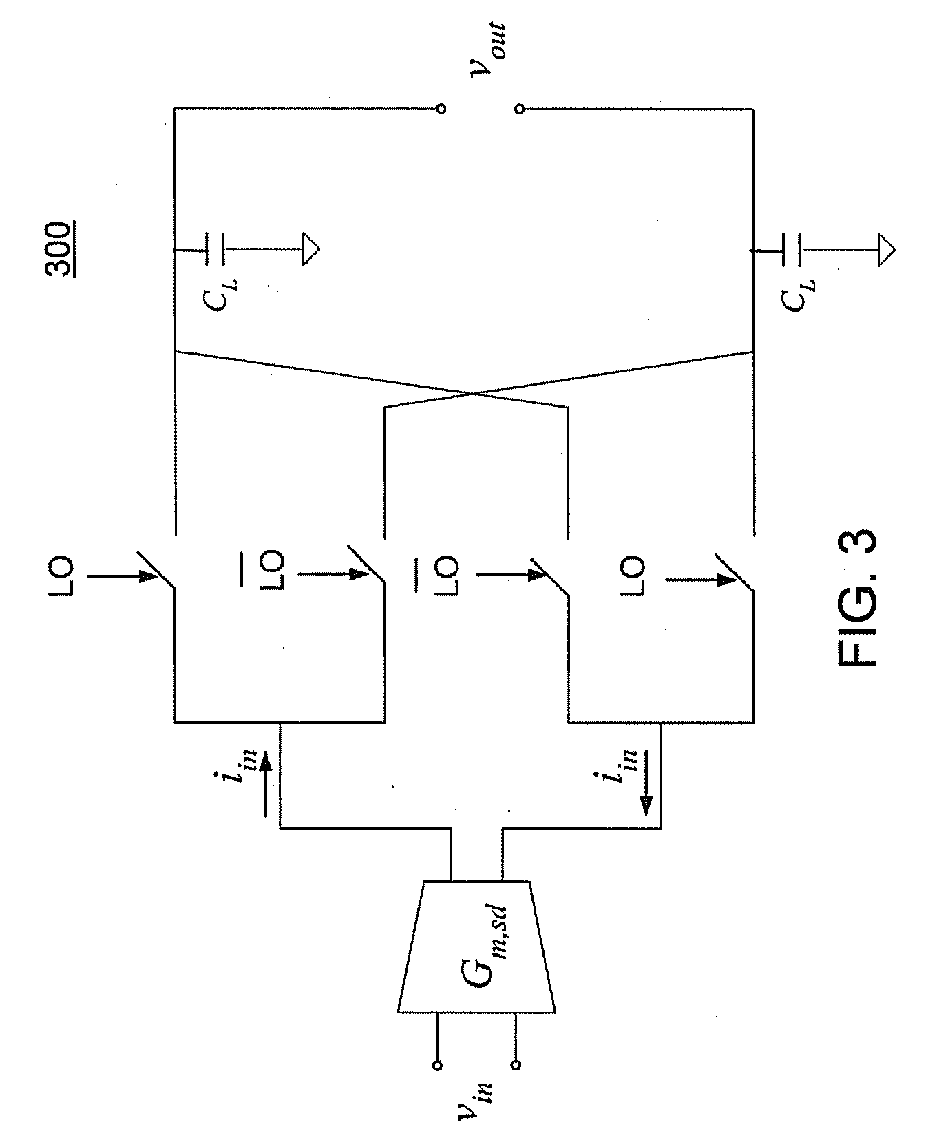
[0026]A current-mode passive mixer 300, 800, 900 with conversion gain that is independent of process, voltage, and temperature (PVT) variation is described below, with reference to FIGS. 3-9. Optionally, the conversion gain may be programmable. Using this technique, the conversion gain of the current-mode passive mixer 300, 800, 900 is proportional to the ratio of the source degeneration capacitance CS to the load capacitance CL. Thus, although the absolute capacitance and other circuit parameters vary with PVT, the ratio of the source degeneration capacitance CS to the load capacitance CL is independent of PVT variation, and so is the mixer conversion gain. In particular, if CS and CL are of the same type of construction, then both are assured to vary in the same manner together in response to any ...


PUM


Abstract

A passive mixer includes a transconductance amplifier having a source degeneration capacitance. The transconductance amplifier has an input for receiving an input signal and an output for outputting a current signal. A multiplier is provided for mixing a local oscillator signal with the current signal so as to provide an output signal at an output of the passive mixer. A capacitive load is connected to the output of the passive mixer.

Description

FIELD OF THE INVENTION[0001]The present invention relates to circuits generally, and more specifically to passive mixers.BACKGROUND[0002]Capacitor banks tuned by calibration circuitry can be applied for process-voltage-temperature (PVT) compensation in passive mixers. FIG. 1 shows the circuit of a double-balanced current-mode passive mixer 100, loaded with tunable capacitor banks C1, C2, . . . , CN. First, the input voltage Vin is converted to current Iin by a transconductance amplifier Gm. Then the current Iin is fed into the switches controlled by complimentary local oscillator (LO) signals, and is accumulated on the load capacitor banks C1, C2, . . . , CN.[0003]The local oscillator (LO) generates complimentary signals which are beat against the signal of interest to mix it to a different frequency. The local oscillator (LO) signals control the switches in mixer 100, while the signal of interest is injected at the input of the mixer 100, to produce the sum and difference of their ...

Claims


Application Information

Patent Timeline
IPC IPC(8): G06G7/12
CPCH03F2203/45488H03F3/45197H03D7/1441H03D7/1458H03D7/1466
Inventor LI, SHAORUICHEN, JINGHONGRIGGE, LAWRENCE
Owner AVAGO TECH INT SALES PTE LTD
Why Eureka
Try Eureka