Bone screw

A bone screw and screw technology, applied in the field of medical devices, can solve the problems of increasing the torque of the bone screw, increasing the torque of screwing in, increasing the difficulty of operation, etc., and achieve the effects of reducing the bearing torque, convenient processing and operation, and reducing the difficulty of operation

Inactive Publication Date: 2014-05-21
DABO MEDICAL TECH CO LTD
View PDF5 Cites 0 Cited by
  • Summary
  • Abstract
  • Description
  • Claims
  • Application Information

AI Technical Summary

Problems solved by technology

However, this bone screw of the prior art adopts the above-mentioned variable-diameter design, although it solves the shortcomings of the traditional bone screw, it also produces new problems: after the variable-diameter design, the tooth front of the deep thread is relatively sharp, and the screw thread cannot be screwed. When screwing in, the resistance is small, but when screwed to the shallow thread at the back of the screw body, the screwing-in resistance is

Method used


Image

  • Bone screw

Examples


Embodiment Construction

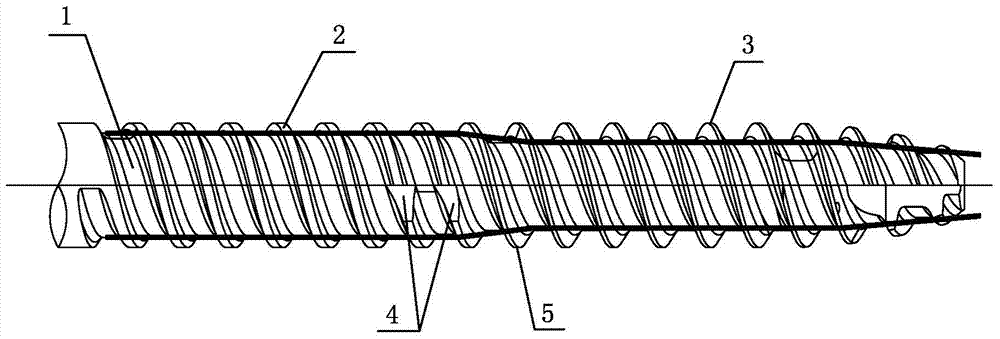
[0019] Examples, see figure 1 As shown, a bone screw of the present invention includes a screw shank 1, which is provided with a screw thread, and the screw thread includes an interconnected front thread and a rear thread, and the rear thread is a shallow thread 2 located in the cortical bone segment. , the front thread is the deep thread 3 located in the cancellous bone segment; the outer diameter of the shallow thread 2 and the deep thread 3 are the same, and the inner diameter of the shallow thread 2 is larger than the inner diameter of the deep thread 3, so that the diameter of the screw shank 1 where the shallow thread 2 is located It is larger than the diameter of the screw shank 1 where the deep thread 3 is located. The front end of the shallow thread 2 is provided with a self-tapping groove 4. Specifically, the radial dimension of the self-tapping groove 4 gradually increases along the direction from the front end of the shallow thread to its rear end, and the groove surf


PUM


Abstract

The invention discloses a bone screw which comprises a screw rod body. Threads are arranged on the screw rod body. The threads include the front-segment thread and the rear-segment thread, wherein the front-segment thread and the rear-segment thread are mutually connected. The front-segment thread is a deep thread, and the rear-segment thread is a shallow thread. The outer diameter of the shallow thread and the outer diameter of the deep thread are equal, and the inner diameter of the shallow thread is larger than the inner diameter of the deep thread. The front end of the shallow thread is provided with a self-tapping groove. According to the bone screw, due to the fact that the self-tapping groove is designed, screw-in and screw-out torsion increased due to reducing of the shallow thread and the deep thread can be reduced, and therefore operation time can be reduced, the operation efficiency and the operation successful rate can be improved, and the risks of nail breaking or device damage are reduced.

Description


Claims


Application Information

Patent Timeline
Owner DABO MEDICAL TECH CO LTD
Why Eureka
Try Eureka