Nanosecond level pulse peak value detection method

A peak detection, nanosecond technology, applied in the field of optical communication, can solve the problems of high cost and complex design of nanosecond pulse peak detection, and achieve the effect of low device cost and lower sampling rate requirements.

Inactive Publication Date: 2014-07-02
BEIJING INSTITUTE OF TECHNOLOGYGY
View PDF5 Cites 4 Cited by
  • Summary
  • Abstract
  • Description
  • Claims
  • Application Information

AI Technical Summary

Benefits of technology

This technology uses a special type of circuit called an LPF (low pass filters) to improve the accuracy at which signals are captured during certain periods when they're being measured or analyzed. By doing this, it becomes easier for these measurements to be done with lower speeds than what was previously possible due to faster analog-converters.

Problems solved by technology

Technological Problem: Current Optical Sampling Methods are limited because they require expensive equipment such as electronics to accurately analyze large amounts of light at very fast speeds. Additionally, current techniques involve capturing only small pulses from one direction over multiple directions simultaneously which requires complex hardware designs.

Method used


Image

  • Nanosecond level pulse peak value detection method
  • Nanosecond level pulse peak value detection method
  • Nanosecond level pulse peak value detection method

Examples


Embodiment Construction

[0017] The implementation of the present invention will be further described in detail below according to the drawings and examples.

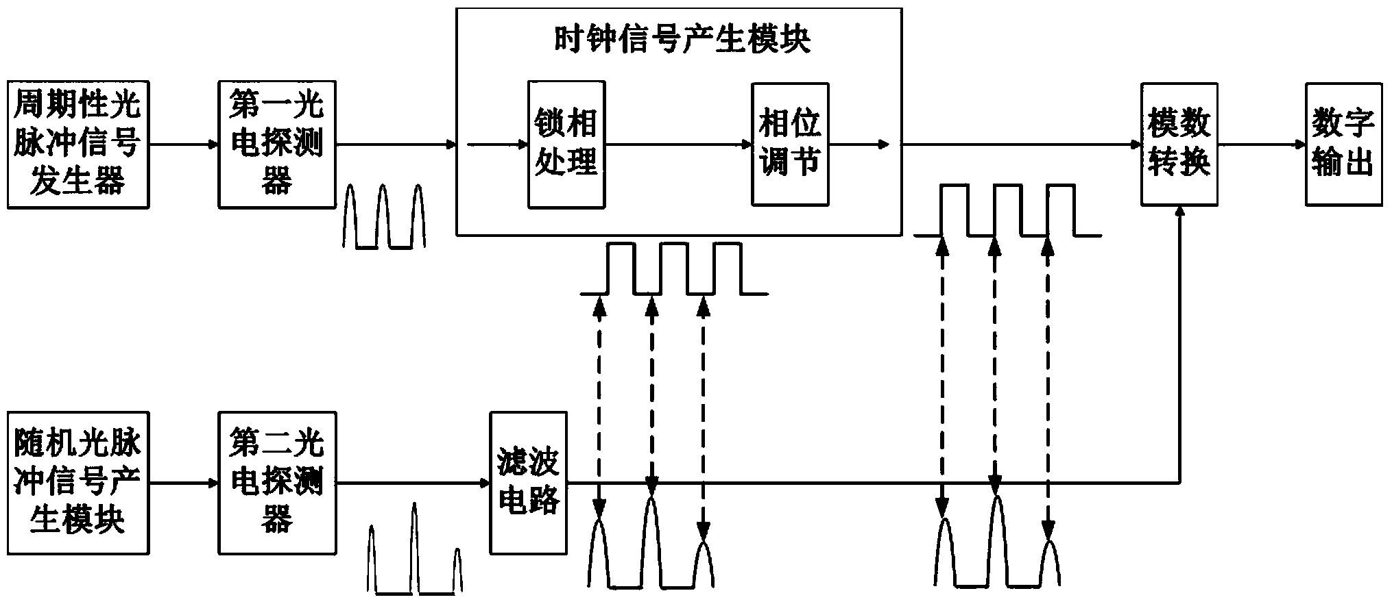
[0018] A nanosecond pulse peak detection system implemented according to a nanosecond pulse peak detection method provided by the present invention is as follows: image 3 As shown, it includes a periodic optical pulse generator, a first photodetector, a second photodetector, a random optical pulse signal generation module, a clock signal generation module, an analog-to-digital converter and a filter circuit. Wherein, the clock signal generation module includes a phase lock processing sub-module and a phase adjustment sub-module.

[0019] The output of the periodic optical pulse generator is connected to the first photodetector, the output of the first photodetector is connected to the phase-lock processing sub-module of the clock signal generation module, the phase-lock processing sub-module is connected to the phase adjustment sub-module, and th


PUM


Abstract

The invention relates to a nanosecond level pulse peak value detection method and belongs to the technical field of optical communication. According to the method, a nanosecond level pulse signal is broadened through a low-pass filter, then, a clock signal obtained after phase position adjustment is triggered, and therefore an analog-digital converter can sample data more accurately. Under the condition that a high-speed analog-digital converter is not needed, a nanosecond level pulse signal peak value can be detected. With the detection method, the requirement for the sampling rate of an analog-to-digital conversion unit can be lowered, the method is simple and easy to perform, and cost of the needed devices is low.

Description


Claims


Application Information

Patent Timeline
Owner BEIJING INSTITUTE OF TECHNOLOGYGY
Why Eureka
Try Eureka