Part quality defect detector and method for detection with same

A technology of quality defects and detectors, applied in the field of mechanical parts inspection, can solve the problems of high price and low measurement accuracy, and achieve the effects of low cost, high degree of automation and convenient use

Inactive Publication Date: 2014-08-13
QILU UNIV OF TECH
View PDF7 Cites 10 Cited by
  • Summary
  • Abstract
  • Description
  • Claims
  • Application Information

AI Technical Summary

Benefits of technology

This technology helps identify faulty areas quickly by automatically scanning them with an infrared sensor or other sensors that don't require any human input like they were used for this purpose.

Problems solved by technology

The technical problem addressed by this patented method is how to accurately determine if there were any hidden areas on machined components without having them touching their surface during testing. This would be useful because expensive devices like those used in industrial settings may have trouble reaching critical locations where they shouldn't even affect performance.

Method used


Image

  • Part quality defect detector and method for detection with same
  • Part quality defect detector and method for detection with same
  • Part quality defect detector and method for detection with same

Examples


Embodiment Construction

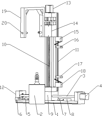
[0016] Accompanying drawing is the specific embodiment of the present invention. Such as Figure 1 to Figure 3 As shown, this kind of parts quality defect detector includes an X-axis slide rail 1, and one side of the X-axis slide rail 1 is connected with a part placement table 2, and an X-axis screw 3 is arranged on the X-axis slide rail 1, and the X-axis wire The two ends of the bar 3 are fixed on the X-axis slide rail 1 through the bearing housing 12, one end of the X-axis screw 3 is connected to the X-axis stepping motor 4, and the left end of the X-axis slide rail 1 is provided with the X-axis left approaching in turn from the inside to the outside. Switch 5 and X-axis left travel switch 6, the right end of X-axis slide rail 1 is provided with X-axis right proximity switch 7 and X-axis right travel switch 8 from inside to outside in sequence, X-axis screw 3 is covered with X-axis slider 9 , the X-axis slider 9 can move back and forth between the X-axis right proximity switch


PUM


Abstract

The invention relates to the field of mechanical part detection, in particular to a part quality defect detector and a method for detection with the part quality defect detector. According to the part quality defect detector and the method for detection with the part quality defect detector, running of stepping motors is controlled by a PLC control system, a laser sensor on the detector is driven to scan parts, data are transmitted to the PLC control system, the collected data are transmitted to a computer, the computer conducts error contrastive analysis on the scanned data and the data of standard parts in a computer database, and the unqualified parts are detected. According to the part quality defect detector and the method for detection with the part quality defect detector, the structure is simple, use is convenient, the cost is low, the degree of automation is high, the defective parts can be detected without contact with the machine parts, and great convenience is brought.

Description


Claims


Application Information

Patent Timeline
Owner QILU UNIV OF TECH
Why Eureka
Try Eureka