Integrated positioning pin hole structure

A combined positioning and positioning pin hole technology, applied in the direction of bolts, etc., can solve the problems of reducing the reliability of the machine, the positioning pin deviates from the correct installation position, and the axial movement range of the positioning pin is large, so as to improve the reliability of the machine and ensure the installation accuracy. , to avoid the effect of difficult assembly

Active Publication Date: 2014-09-03
GUANGXI YUCHAI MASCH CO LTD
View PDF10 Cites 0 Cited by
  • Summary
  • Abstract
  • Description
  • Claims
  • Application Information

AI Technical Summary

Problems solved by technology

[0002] like figure 1 As shown, for a class of parts A, B, and C that are stacked with multiple parts and require precise relative positions, B itself needs to be installed on part A, and part C is installed on part B, and parts B, B, and C are connected by bolts. Part C is fixed on part A. In order to ensure that the installation position of the part is accurate and to avoid the failure of the bolt to be installed due to the serious misalignment of the part, part B needs to be accurately positioned with part A through the positioning pin, and part C also needs to be accurately positioned with part B through the positioning pin. Positioning, existing practices such as figure 2 , image 3 as shown, figure 2 As shown, the two positioning pin holes are independent and not related to each other. Since a common bolt connection is required, this structure cannot guarantee coaxiality, and the parts cannot be positioned accurately
In severe cases, the bolt holes will also be misplaced, making it difficult to install parts
image 3 The two pin holes shown in the figure are connected, and the coaxial stepped holes are made to ensure that the two pin holes are coaxial, but the axial movement range of the positioning pin is relatively large. During the use of the machine, the positioning pin may deviate from the correct installation due to vibration. Position, lose positioning function, reduce machine reliability
Moreover, when using this structure, when assembling the positioning pin, it may be necessary to rework due to improper operation, which wastes man-hours and affects the production cycle.

Method used


Image

  • Integrated positioning pin hole structure
  • Integrated positioning pin hole structure
  • Integrated positioning pin hole structure

Examples


Embodiment 1

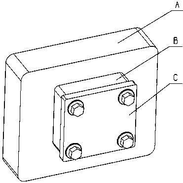
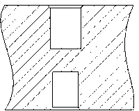
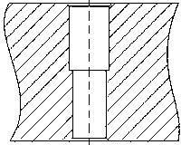
[0021] Embodiment 1, by adding an appropriate limit boss in the middle of the two pin holes, and optimizing the size combination, it can not only ensure the coaxiality of the two pin holes, but also limit the axial movement of the two positioning pins in an acceptable range. within range. Accurate positioning of parts is realized, which prevents the installation size of related parts from being out of tolerance due to inaccurate assembly positions of the parts themselves, which affects the quality of the whole machine. The positioning failure caused by the axial movement of the positioning pin during use is avoided, and the reliability of positioning is improved. It also avoids assembly difficulties caused by misalignment of parts or incorrect positioning pin installation operations, which affects production beats. The cylinder block 1, the gear chamber 2 and the gear chamber cover 3 are connected and fastened by connecting bolts 4, and are positioned and connected by using t...

Embodiment 2

[0022] Embodiment 2, a combined positioning pin hole structure of the present invention, including cylinder block 1, gear chamber 2, gear chamber cover 3, connecting bolts 4 (multiple), small positioning pins 5 (two), large positioning pins 6 ( two). The gear chamber 2 is installed on the cylinder block 1, the gear chamber cover 3 is installed on the gear chamber 2, and is fixed by connecting bolts 4, the gear chamber 2 is accurately positioned on the cylinder block 1 by the large positioning pin 6, and the gear chamber cover 3 is positioned by the small positioning pin The pin 5 is positioned precisely on the gear chamber 2 . The positioning pin hole on the gear chamber 2 adopts the structure of the present invention, the two pin holes are coaxial, and the center is designed with a spacer boss. A limited boss is designed in the middle of the two coaxial positioning pin holes. The boss height (relatively small pin hole) h, h is preferably (0.5~1). a=L-(a+b), b, c, and H ...


PUM


Abstract

The invention discloses an integrated positioning pin hole structure. The integrated positioning pin hole structure comprises a cylinder body, a gear chamber, a gear chamber cover, connecting bolts, small positioning pins, large positioning pins, a boss, a large positioning pin hole, a small positioning pin hole, a part clamping width and a boss height. The integrated positioning pin hole structure is characterized in that the gear chamber and the gear chamber cover are fastened to the cylinder body through the connecting bolts; the large positioning pin installation hole and the small positioning pin installation hole are located on the same axial line, so that the problems that every two positioning pins are installed in an unrelated mode, coaxial parts can not be accurately positioned, bolt holes are misaligned, the parts can not be installed, the positioning pins move axially and fail to function, and assembly uncertainty causes reworking waste and affects product are solved. The coaxiality of the two positioning pin holes is guaranteed, installation accuracy of the parts is also guaranteed, axial displacement of the positioning pins is effectively limited within a certain range, and the integrated positioning pin hole structure is simple in structure, easy to machine, practical and reliable.

Description

technical field [0001] The invention relates to a positioning structure, in particular to a combined positioning pin hole structure. Background technique [0002] Such as figure 1 As shown, for a class of parts A, B, and C that are stacked with multiple parts and require precise relative positions, B itself needs to be installed on part A, and part C is installed on part B, and parts B, B, and C are connected by bolts. Part C is fixed on part A. In order to ensure that the installation position of the part is accurate and to avoid the failure of the bolt to be installed due to the serious misalignment of the part, part B needs to be accurately positioned with part A through the positioning pin, and part C also needs to be accurately positioned with part B through the positioning pin. Positioning, existing practices such as figure 2 , image 3 as shown, figure 2 As shown, the two positioning pin holes are independent and not related to each other. Since a common bolt is...

Claims


Application Information

Patent Timeline
IPC IPC(8): F16B19/02
Inventor 粟荣锦覃文覃壮革
Owner GUANGXI YUCHAI MASCH CO LTD
Why Eureka
Try Eureka