Refraction and reflection omnidirectional image restoration method with mirror surface parameter constraining blurring kernels

An omnidirectional image and parameter constraint technology, applied in image enhancement, image data processing, instruments, etc., can solve problems such as limiting image restoration effect, and achieve the effect of improving the effect

Active Publication Date: 2014-09-24
NAT UNIV OF DEFENSE TECH
View PDF3 Cites 1 Cited by
  • Summary
  • Abstract
  • Description
  • Claims
  • Application Information

AI Technical Summary

Problems solved by technology

Therefore, it is difficult for traditional image restoration techniques to accurately analyze and describe the defocus blur of

Method used


Image

  • Refraction and reflection omnidirectional image restoration method with mirror surface parameter constraining blurring kernels
  • Refraction and reflection omnidirectional image restoration method with mirror surface parameter constraining blurring kernels
  • Refraction and reflection omnidirectional image restoration method with mirror surface parameter constraining blurring kernels

Examples


Example Embodiment

[0046] Such as Figure 5 As shown, this embodiment adopts Image 6 The catadioptric imaging system shown collects image data. In the imaging system, the camera is Canon5D Mark II, the lens is a 50mm F / 1.8 Canon lens, the aperture is set to F / 1.8, and 7.5 million pixel omnidirectional images are collected. The focus is set at the front end of the catadioptric mirror, and the catadioptric mirror is double For curved surface, the parameters are a=22.3mm, b=22.3mm, and c=31.5mm. The acquired defocused and blurred omnidirectional image such as Figure 7 Shown.

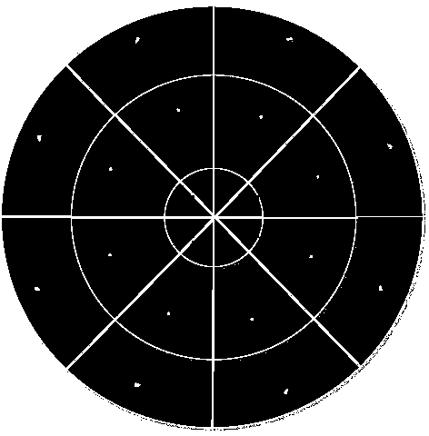
[0047] Such as image 3 As shown, the ring and block operations are performed on the collected omnidirectional image. For the ring operation, the specific process is: the origin of the image is the center and the radius is r k To radius r k The area of ​​+Δr is the kth ring, and the width of each ring is equal. Where r k Represents the inner ring radius of the k-th ring, Δr represents the width of the ring, and k represents


PUM


Abstract

The invention discloses a refraction and reflection omnidirectional image restoration method with mirror surface parameter constraining blurring kernels. Under the framework of the maximum posterior probability image restoration theory, according to the characteristics of a refraction and reflection imaging system, blurring kernel constraints, namely the rotating symmetry constraint and the spatial transformation constraint, for a refraction and reflection imaging model are provided. According to the refraction and reflection omnidirectional image restoration method, the good omnidirectional image restoration effect is obtained through new blurring kernel constraint terms.

Description


Claims


Application Information

Patent Timeline
Owner NAT UNIV OF DEFENSE TECH
Why Eureka
Try Eureka