Elevator brake of novel structure

A technology of elevator brake and new structure, which is applied in hoisting devices and other directions, can solve the problems of increased process difficulty, increased processing difficulty, and high cost, and achieves the effects of easy manufacturing, low design and processing costs, and less material waste

Active Publication Date: 2014-10-08
成都瑞迪智驱科技股份有限公司
View PDF3 Cites 3 Cited by
  • Summary
  • Abstract
  • Description
  • Claims
  • Application Information

AI Technical Summary

Benefits of technology

In this patented system for mounting brackets onto electric motors it involves combining several parts together into an improved fixed position. These simplifying features help make them easier to produce while also reducing their complexity compared to traditional methods like welded connections between metal plates. Additionally, these systems have multiple types of materials used instead of just two, saving money over time. Overall, they provide technical benefits such as increased flexibility, reduced fabrication requirements, enhanced efficiency, and reduction of production costs.

Problems solved by technology

This patented technical problem addressed in this patents relates to improving the performance (cost effect) of an electric motor used in elevators due to the size constraints associated therewith. Specifically, it focuses on reducing costs without sacrificing efficiency when designing new components such as the magnetic core and the sliding block mechanism.

Method used


Image

  • Elevator brake of novel structure
  • Elevator brake of novel structure
  • Elevator brake of novel structure

Examples


Embodiment Construction

[0023] The present invention will be further described below in conjunction with accompanying drawing.

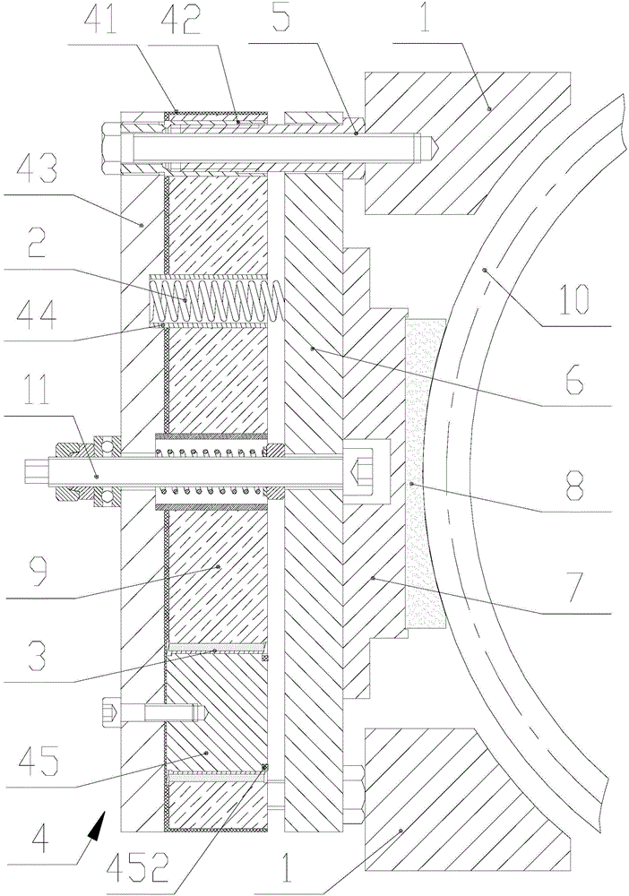
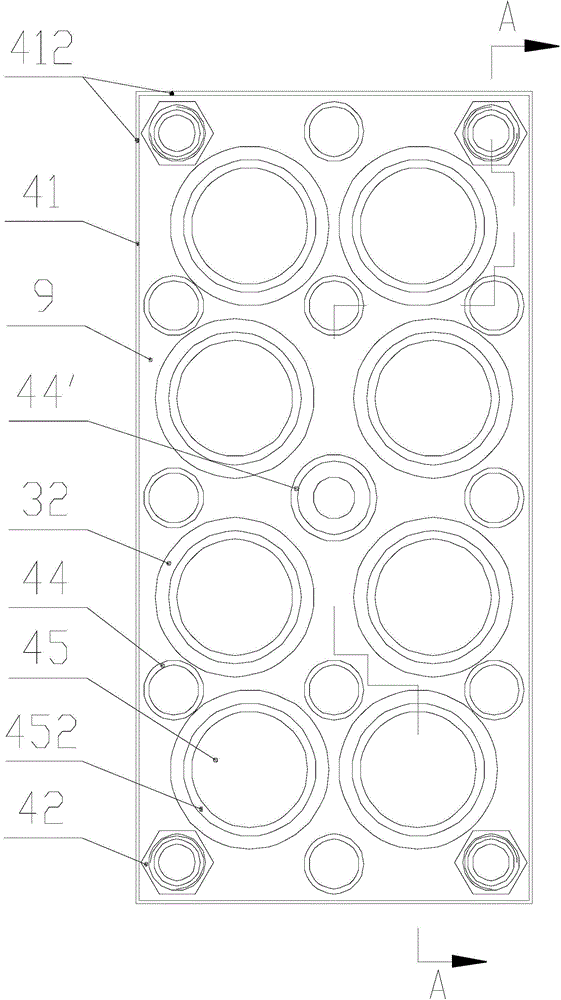
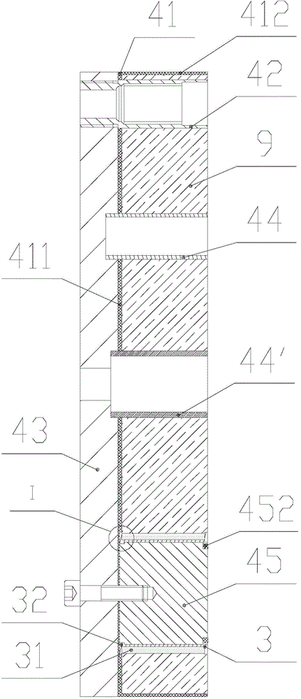
[0024] Such as figure 1 and figure 2 As shown, a new type of elevator brake includes a hub 1, a spring 2, a coil winding 3, a guide post 5, an armature 6, a tongue plate 7 and a friction plate 8 arranged on the tongue plate 7, and the armature 6 is installed On the guide post 5 and can move along the guide post 5, the tongue plate 7 is fixed on the armature 6, the brake also includes an assembly fixing seat 4, and the assembly fixing seat 4 includes a frame shell 41, a fixing plate 43, a spring fixing Cover 44 and iron core 45; the frame shell 41 and the spring fixing sleeve 44 are all arranged on the fixed plate 43; the iron core 45 is at least one, and the iron core 45 is arranged on the fixed plate 43 and is located in the frame shell 41; The coil winding 3 is arranged on the iron core 45, the two ends of the guide post 5 are respectively fixedly connected to the fixed p


PUM


Abstract

The invention discloses an elevator brake of a novel structure. The elevator brake of the novel structure is low in cost and comprises an installation hub, a spring, coil windings, a guide column, an armature, a tongue plate and a friction plate arranged on the tongue plate. The armature is installed on the guide column and can move along the guide column. The tongue plate is fixed to the armature. The brake further comprises an assembly fixing base which comprises a frame shell, a fixing plate, a spring fixing sleeve and at least one iron core. The frame shell and the spring fixing sleeve are both arranged on the fixing plate. The iron cores are arranged on the fixing plate and located in the frame shell. The coil windings are arranged on the iron cores. The two ends of the guide column are fixedly connected to the fixing plate and the installation hub respectively. The spring is arranged in the spring fixing sleeve and located between the fixing plate and the armature. Compared with an integrated groove disc, components of the assembly fixing base are simple in structure, machining cost is low, material waste caused in the machining process is smaller, and cost is lower.

Description


Claims


Application Information

Patent Timeline
Owner 成都瑞迪智驱科技股份有限公司
Why Eureka
Try Eureka