Current mirror for low supply voltage

A low power supply voltage, current mirror technology, applied in the field of current mirror, can solve the problems of unsuitable current mirror circuit and reduced voltage margin, etc.

Inactive Publication Date: 2014-10-08
UNIV OF ELECTRONICS SCI & TECH OF CHINA
View PDF5 Cites 16 Cited by
  • Summary
  • Abstract
  • Description
  • Claims
  • Application Information

AI Technical Summary

Benefits of technology

This technology can be used with lower voltages but still improve its performance by reducing electrical interference from other devices connected through an AC line.

Problems solved by technology

This patented technical problem addressed by this patents relates to improving the performance of current mirrors when operating with lower voltages due to their limited ability to handle high currents without causing damage during operation.

Method used


Image

  • Current mirror for low supply voltage
  • Current mirror for low supply voltage
  • Current mirror for low supply voltage

Examples


Embodiment Construction

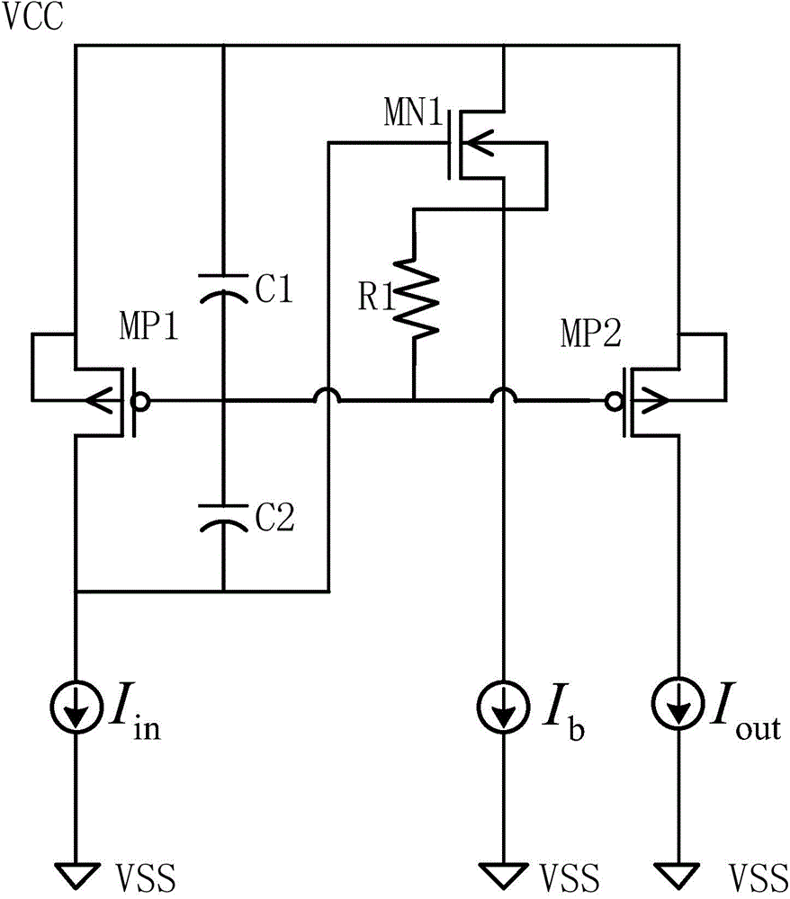
[0013] The specific embodiment of the present invention is described below in conjunction with accompanying drawing

[0014] Such as figure 2 As shown, the current mirror of the present invention is composed of PMOS transistors MP1, MP2, NMOS transistor MN1, capacitors C1, C2, resistor R1, input current source, output terminal current source and bias current source; wherein, the source of MP1 is connected to Power supply VCC, its gate is connected to the gate of MP2, its drain is connected to the positive pole of the input current source; the negative pole of the input current source is grounded to VSS; the drain of MN1 is connected to the power supply VCC, its gate is connected to the positive pole of the input current source, and its source The pole is connected to the positive pole of the bias current source, and its substrate is connected to the connection point between the gate of MP1 and the gate of MP2 through R1; the negative pole of the bias current source is grounded t


PUM


Abstract

The invention relates to the technical field of integrated circuits, in particular to a current mirror. The current mirror is characterized in that the current mirror is composed of a PMOS transistor MP1, a PMOS transistor MP2, an NMOS transistor MN1, a capacitor C1, a capacitor C2, a resistor R1, an input current source, an output end current source and a bias current source. The source electrode of the MP1 is connected with a power source VCC, the grid electrode of the MP1 is connected with the grid electrode of the MP2, and the drain electrode of the MP1 is connected with positive electrode of the input current source. The negative electrode of the input electrode source is grounded VSS. The drain electrode of the MN1 is connected with the power source VCC, the grid electrode of the MN1 is connected with the positive electrode of the input current source, the source electrode of the MN1 is connected with the positive electrode of the bias current source, and the substrate of the MN1 is connected with a connection point of the grid electrode of the MP1 and the grid electrode of the MP2 through the R1. A connection point of the source electrode of the MP1 and the drain electrode of the MN1 is connected with a connection point of the grid electrode of MN1 and the positive electrode of the input current source through the C1 and the C2 sequentially. The source electrode of the MP2 is connected with the power source VCC, and the drain electrode of the MP2 is connected with the positive electrode of an output current source. The current mirror has the advantages of being suitable for being used under low supply voltage, meanwhile improving the PSR of the current mirror, and being especially suitable for a current mirror circuit.

Description


Claims


Application Information

Patent Timeline
Owner UNIV OF ELECTRONICS SCI & TECH OF CHINA
Why Eureka
Try Eureka