Brushless plastic motor and manufacturing method thereof

A plastic and injection molding technology, which is applied in the manufacture of motor generators, electrical components, electromechanical devices, etc., can solve the problems of long processing time for the shell of brushless plastic motors, high motor production costs, and complicated production processes, etc., to achieve processing The effect of process reduction, manufacturing cost reduction, and simplified structure

Active Publication Date: 2014-11-05
DONGGUAN YINYAN ELECTRICAL SCI & TECH CO LTD
View PDF6 Cites 8 Cited by
  • Summary
  • Abstract
  • Description
  • Claims
  • Application Information

AI Technical Summary

Problems solved by technology

[0003] The purpose of the present invention is to provide a brushless plastic motor and its manufacturing method, aiming to solve the problem of long shell processing time,

Method used


Image

  • Brushless plastic motor and manufacturing method thereof
  • Brushless plastic motor and manufacturing method thereof
  • Brushless plastic motor and manufacturing method thereof

Examples


Embodiment Construction

[0028] In order to make the object, technical solution and advantages of the present invention clearer, the present invention will be further described in detail below in conjunction with the accompanying drawings and embodiments. It should be understood that the specific embodiments described here are only used to explain the present invention, not to limit the present invention.

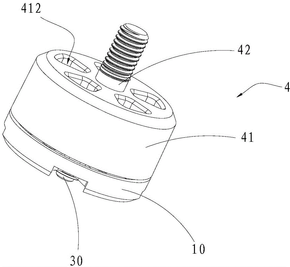
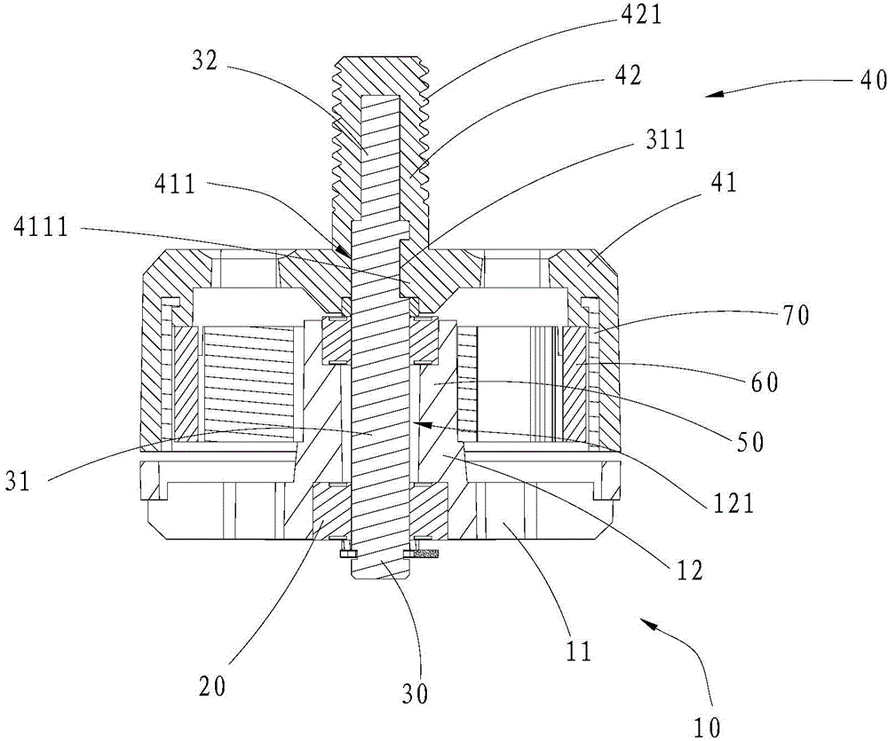
[0029] Such as Figure 1 to Figure 4 As shown, it is a schematic diagram of a brushless plastic motor provided by an embodiment of the present invention, which includes an injection-molded bottom case 10. Specifically, the bottom case 10 includes a bottom plate portion 11 and a protruding portion protruding from the bottom plate portion 11. 12. The protruding part 12 is provided with an axial through hole 121, and the two ends of the axial through hole 121 are embedded with bearings 20. The brushless plastic motor provided in this embodiment also includes a bearing hole pierced through the bearing 20.


PUM


Abstract

The invention is applicable to the field of brushless motors, and discloses a brushless plastic motor. The brushless plastic motor comprises an injection moulding bottom housing, a rotating shaft, an injection moulding head cover, a stator, a magnet and a tube, wherein the bottom housing comprises a bottom plate part and a convex extending part; an axial through hole is formed in the convex extending part; bearings are arranged in ports of the two ends of the axial through hole in an embedding manner; the rotating shaft is arranged on the bearings in a penetrating manner; the head cover is arranged on the rotating shaft in a sleeving manner; the stator is arranged on the convex extending part of the bottom housing in a sleeving manner; the magnet is arranged on the stator in a sleeving manner; the tube is arranged on the magnet in a sleeving manner; and the head cover is butted with the bottom housing. According to the brushless plastic motor, the bottom housing provided with the convex extending part and the head cover provided with an inner cavity are adopted, the rotating shaft penetrates through the convex extending part of the bottom housing and then is butted with the head cover, the stator, the magnet and the tube are contained in the inner cavity of the head cover, and the bottom housing and the head cover adopt injection moulding and serve as protective housings and mounting carriers of components, so that the structure of the brushless motor is simplified greatly, the processing procedure and the processing time of the brushless motor are reduced greatly, and the production efficiency is improved greatly.

Description


Claims


Application Information

Patent Timeline
Owner DONGGUAN YINYAN ELECTRICAL SCI & TECH CO LTD
Why Eureka
Try Eureka