Transmission shaft for machine tool transmission system

A machine tool transmission and transmission shaft technology, applied in the field of transmission shafts, to achieve good dynamic balance performance, simple structure, and long service life

Inactive Publication Date: 2015-02-04
包文波
View PDF8 Cites 0 Cited by
  • Summary
  • Abstract
  • Description
  • Claims
  • Application Information

AI Technical Summary

Benefits of technology

This patented technology allows for better control over rotation speed by combining two types of drive systems - one system uses only motor power while another system uses both motors at once. By doing this, it improves overall efficiency and reduces maintenance costs compared to traditional methods like hydraulic or pneumatic cylinders used alone.

Problems solved by technology

This patented technical problem addressed in this patents relates to improving the stability of an electric motor used for driving machines during machining operations by adding support structures or other means that help maintain static equilibrium between different parts within the drive train.

Method used


Image

  • Transmission shaft for machine tool transmission system

Examples


Embodiment Construction

[0011] The technical scheme of the present invention will be described in further detail below in conjunction with the accompanying drawings and specific embodiments, so that those skilled in the art can better understand the present invention and implement it, but the examples given are not intended to limit the present invention.

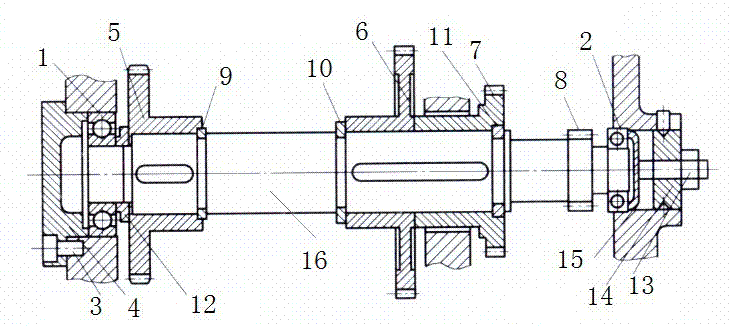
[0012] Such as figure 1 As shown, a transmission shaft of a machine tool transmission system includes a central shaft 16, one end of the central shaft 16 is provided with a front bearing 1, and the other end is provided with a rear bearing 2, and the outer side of the front bearing 1 is fixed with an end cover 4, and the rear bearing 2 A top cover 15 is fixed on the outside. Preferably, the end cover 4 is fixed on the front bearing 1 by screws 3 .

[0013] The central shaft 16 is sequentially provided with a first gear 5, a first retaining ring 9, a second retaining ring 10, a second gear 6, a third gear 7, and a third retaining ring 11 from the fro


PUM


Abstract

The invention discloses a transmission shaft for a machine tool transmission system. The transmission shaft comprises a center shaft, wherein one end of the center shaft is provided with a front bearing, the other end of the center shaft is provided with a back bearing, the outer side of the front bearing is fixedly provided with an end cover, and the outer side of the back bearing is fixedly provided with a top cover. The transmission shaft is characterized in that the center shaft is sequentially provided with a first gear, a first baffle ring, a second baffle ring, a second gear, a third gear, a third baffle ring and a fourth gear from the front bearing to the back bearing, the first gear is connected with the first baffle ring, the second baffle ring is connected with the second gear, the third gear is connected with the third baffle ring, a separation sleeve is arranged between the first gear and the front bearing, and the back bearing end is provided with a plug used for sealing. The transmission shaft has the advantages that good dynamic balance performance is realized, in addition, the structure is simple, and the service life is long.

Description


Claims


Application Information

Patent Timeline
Owner 包文波
Why Eureka
Try Eureka