Projectile simulation launching device

A technology for simulating launching and projectiles, applied in the direction of launching devices, etc., to achieve the effect of improving the quality and efficiency of experiments and high repeatability

Inactive Publication Date: 2015-03-11
高显明
View PDF6 Cites 2 Cited by
  • Summary
  • Abstract
  • Description
  • Claims
  • Application Information

AI Technical Summary

Problems solved by technology

However, the launch of electromagnetic guns requires a high-performance pulse power supply net

Method used


Image

  • Projectile simulation launching device
  • Projectile simulation launching device
  • Projectile simulation launching device

Examples


Embodiment 1

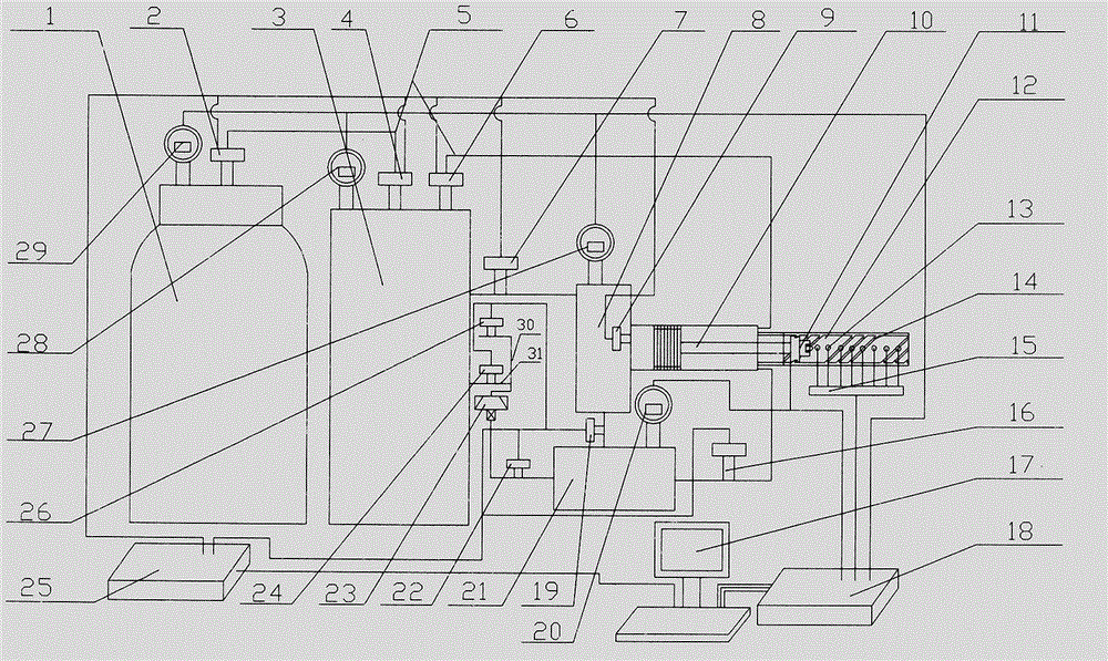
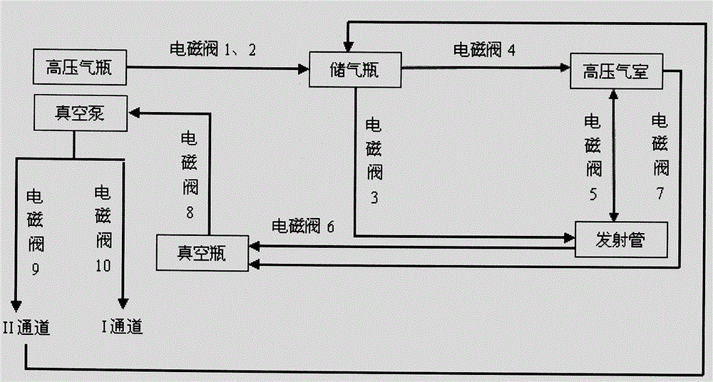
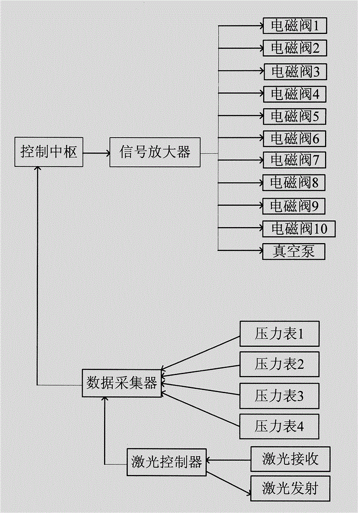
[0015] 1. The device of the present invention includes air cannon launch, pressure relief brake control, speed control and speed measuring device unit; air cannon launch unit includes high pressure air chamber 8, launch tube 12, piston assembly 10 and bullet holder 11; pressure relief brake control unit Including gas cylinder 3, solenoid valve 7-19, solenoid valve 6-16, solenoid valve 3-6, data collector 18, signal amplifier 25 and control center 17; speed control unit includes bullet holder 11 and launch tube rifling 14; speed measuring device unit Including laser emitting and receiving device 13, laser controller 15, data collector 18 and control center 17 (such as figure 1 shown). The specific mechanical connection method is as follows (such as figure 1 ):

[0016] High-pressure gas cylinder 1 is connected with pressure gauge 4 29 and solenoid valve 1 2, gas storage cylinder 3 is connected with pressure gauge 328, solenoid valve 2 4 and solenoid valve 3 6, and high-pressure


PUM


Abstract

The invention discloses a projectile simulation launching device, and belongs to the field of the armament science and technology. The device comprises a gas gun launching unit, a pressure relief brake control unit, a rotating speed control unit and a speed measuring device unit; the gas gun launching unit comprises a high-pressure gas chamber, a launching pipe, a piston component and a projectile support; the pressure relief brake control unit comprises a gas storage bottle, an electromagnetic valve (7), an electromagnetic valve (6), an electromagnetic valve (3), a data acquisition unit, a signal amplifier and a control main center; the rotating speed control unit comprises the projectile support and a launching pipe rifling; and the speed measuring device unit comprises a laser launching and receiving device, a laser controller, the data acquisition unit and the control main center. The projectile simulation launching device has the beneficial effect of close-range, high-precision, high-repeatability and environment-friendly launching and meets the requirement of the finish effect test study.

Description


Claims


Application Information

Patent Timeline
Owner 高显明
Why Eureka
Try Eureka