Metal cutting tool

A metal cutting and cutting tool technology, applied in the field of mold manufacturing, can solve the problems of not being able to extend the tool handle at any time, inconvenient use, and low production efficiency, and achieve the effects of saving a lot of time, convenient use, and improving work efficiency

Inactive Publication Date: 2015-03-18
TIANJIN JINSHENGDE METAL PROD
View PDF0 Cites 0 Cited by
  • Summary
  • Abstract
  • Description
  • Claims
  • Application Information

AI Technical Summary

Benefits of technology

This new design allows for better performance by providing both tools that replace older ones without requiring changes or adjustments after they have been used once again. It achieves this through adding extra parts like slices instead of just one single bit. Additionally, it includes a mechanism where each part fits into place securely but still works properly if needed. Overall, these improvements make working faster while reducing costs compared to previous designs.

Problems solved by technology

This patented technical problem addressed in this patents relates to finding an effective way to remove small pieces made by machining metals without having them stick out or being damaged during their removal process. Existing methods have limitations such as weak blades that may damage materials when they come off too much; lacking flexibility with changing between multiple positionings while also reducing productivity due to frequent changes required.

Method used


Image

  • Metal cutting tool

Examples


Embodiment Construction

[0011] The present invention will be described in detail below with reference to the accompanying drawings and in combination with embodiments.

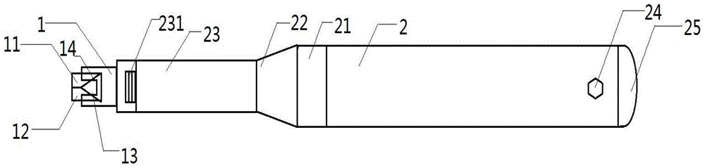
[0012] figure 1 It shows a schematic structural diagram of a metal cutting tool according to an embodiment of the present invention;

[0013] Such as figure 1 As shown, a metal cutting tool includes a cutter head 1 and a handle 2. The cutter head 1 is arranged at one end of the handle 2. The cutter head 1 includes an outer cutter 11, an inner hole cutter 12, a first sipe 13 and a second The knife groove 14 , the first knife groove 13 is perpendicular to the second knife groove 14 , and the knife handle 2 includes a knife head locking device 21 and a knife head fixing device 22 .

[0014] The knife handle 2 also includes an extension rod 23 , which is provided with a screw thread and adapted to the cutter head 1 .

[0015] The knife handle 2 also includes a buckle hole 24 and a knife head storage device 25 , and the buckle hole 24 fix


PUM


Abstract

The invention provides a metal cutting tool. The metal cutting tool comprises a tool bit and a tool handle, the tool bit is arranged at one end of the tool handle and comprises an outer cutter, an inner bore cutter, a first cutter groove and a second cutter groove, the first cutter groove is perpendicular to the second cutter groove, and the tool handle comprises a tool bit locking device and a tool bit fixing device. Due to replacement of an original one cutter with two cutters and arrangement of the first cutter groove and the second cutter groove, cutter amount can be increased with cutter position unchanged, and cutter change is not needed during cutting of inner bores, so that procedures are simplified, a great deal of time is saved, and operation efficiency is improved. Moreover, since the tool handle is provided with the locking device and the fixing device, stress uniformity in use can be achieved; owing to an extension rod arranged on the tool handle, the tool handle can be lengthened in special occasions, so that the metal cutting tool is more convenient to use and more humanized.

Description


Claims


Application Information

Patent Timeline
Owner TIANJIN JINSHENGDE METAL PROD
Why Eureka
Try Eureka