Resistance detection device for wire winding machine

A technology of resistance detection and wire winding machine, which is applied in measurement devices, measurement of resistance/reactance/impedance, measurement of electrical variables, etc., can solve the problems of troublesome detection and low production efficiency, and achieve the effect of convenient detection and high detection efficiency.

Inactive Publication Date: 2015-04-22
何雲彬
View PDF7 Cites 1 Cited by
  • Summary
  • Abstract
  • Description
  • Claims
  • Application Information

AI Technical Summary

Benefits of technology

In this new design, there are two parts - a rotary chuck with a special part called the hot-wire contactor (HCR) – where it connects another piece of equipment like electricity or gas pipelines during manufacturing processes. When we wind up these cables, they create connections between them through their own HCR' s unique features. These connections allow us to test how well the cable works by connecting different pieces together without removing any components from its original location.

Problems solved by technology

This patented technical problem addressed by this patents relating to improving the process of producing electrical devices such as electric heatings or electronic components involves making sure that there's no damage caused during manufacturing due to excessive current flow through any conductors within them when they shouldn’t be affected (such as overheated). Additionally, monitoring how well these resistances meet specific standards can help improve productivity while reducing labor costs associated with testing each component separately.

Method used


Image

  • Resistance detection device for wire winding machine
  • Resistance detection device for wire winding machine
  • Resistance detection device for wire winding machine

Examples


Embodiment Construction

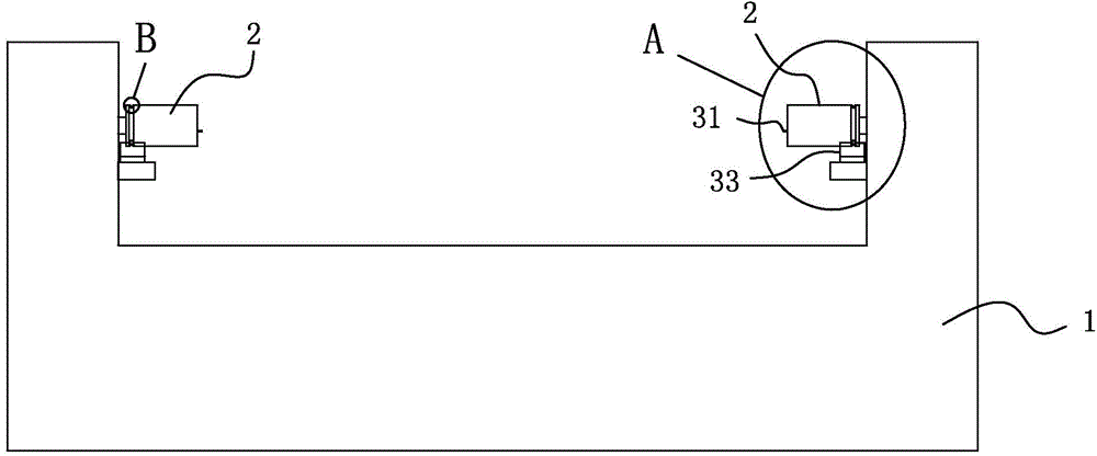
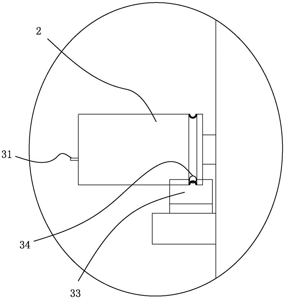
[0018] refer to Figure 1 to Figure 5 , the resistance detection device of a kind of wire winding machine of the present invention, comprises the rotatable rotating collet 2 that is used for clamping the wire wrapping board that is located at both ends of frame 1, and described rotary collet 2 is provided with and rotary collet 2 Insulate and extend the conductive tongue 31 of the rotary chuck 2, and the circular groove 21 surrounding the rotation center of the rotary chuck 2, the circular groove 21 is surrounded by a conductor 32 insulated from the rotary chuck 2, the conductor 32 Electrically connected with the conductive tongue 31, the two ends of the frame 1 are respectively provided with an insulating frame 33 below the rotary chuck 2, and the insulating frame 33 is provided with all conductors 32 on the same side of the frame to form an electrical connection. Outlet 34. In this structure, since the conductor 32 surrounds the annular groove 21 , the contact between the cond


PUM


Abstract

The invention discloses a resistance detection device for a wire winding machine. The resistance detection device comprises rotatable spin chucks which are arranged at the two ends of a rack and are used for clamping a wire winding plate, wherein each spin chuck is provided with an electroconductive tongue piece which is insulated from the spin chuck and extends out of the spin chuck, and an annular groove surrounding the rotating center of the spin chuck, and an electric conductor insulated from the spin chuck is arranged in the annular groove in a surrounding way; the electric conductor is electrically connected with the electroconductive tongue piece, and insulation racks are respectively arranged below the spin chucks at the two ends of the rack; the insulation racks are provided with leading-out terminals electrically connected with all electric conductors at the same side of the rack in a contact way. When the detection is carried out, one end of the resistance detection instrument is electrically connected with the leading-out terminal to form a common terminal, and the other end of the resistance detection instrument is electrically connected with the electroconductive tongue piece corresponding to the other end of an electric heating wire to be detected in a contact way, so that the size of resistance value of the corresponding electric heating wire can be detected; the wiring measurement can be carried out without disassembling the wire winding plate, so that the detection is convenient, and the detection efficiency is high.

Description


Claims


Application Information

Patent Timeline
Owner 何雲彬
Why Eureka
Try Eureka