Heater pipeline structure of roasting furnace

A heater and roaster technology, which is applied to burners, lighting and heating equipment, gas fuel burners, etc., can solve the problems of poor gas combustion effect and high energy consumption

Inactive Publication Date: 2015-04-29
WUXI KANGHUI MACHINE BUILDING
View PDF0 Cites 0 Cited by
  • Summary
  • Abstract
  • Description
  • Claims
  • Application Information

AI Technical Summary

Problems solved by technology

Among them, the roaster is the main equipment for thermal regeneration, and its structural performance directly affects the quality of recycled sand. However, the effect of the traditional roaster is not ideal. Usually, the furnace body of the

Method used


Image

  • Heater pipeline structure of roasting furnace

Examples


Embodiment Construction

[0012] The present invention will be described in further detail below according to the drawings and embodiments.

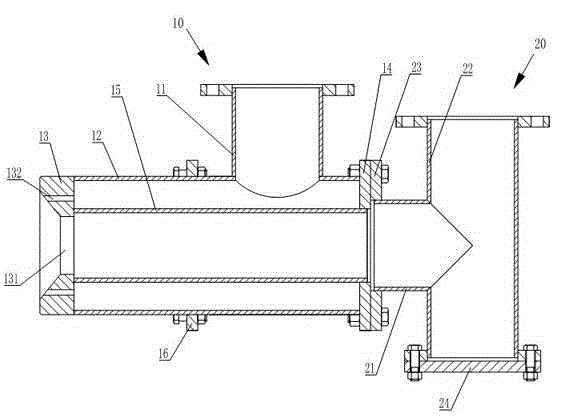
[0013] like figure 1 As shown, the heater pipe body structure of a baking furnace according to the embodiment of the present invention includes a secondary air inlet pipe 10 and a gas inlet pipe 20, and the secondary air inlet pipe 10 includes air valve connecting pipes 11 connected to each other. And air inlet main pipe 12, one end of described air inlet main pipe 12 is fixedly connected with burner 13, and the other end of described air inlet main pipe 12 is provided with connecting flange A 14; Described air inlet main pipe 12 is provided with inner pipe 15 , one end of the inner pipe 15 is fixedly connected to the burner 13, and the other end of the inner pipe 15 is fixedly supported by the connecting flange 14; the burner 13 has a gas nozzle 131 and an air nozzle 132, One end of the inner pipe 15 communicates with the gas nozzle 131 , and the other end of the


PUM


Abstract

The invention relates to a heater pipeline structure of a roasting furnace. The heater pipeline structure comprises a secondary air inlet pipe and a fuel gas inlet pipe. The secondary air inlet pipe comprises an air valve connecting pipe and a main air inlet pipe which are communicated. A burner is fixedly connected to one end of the main air inlet pipe. A first connecting flange is arranged at the other end of the main air inlet pipe. An inner pipe is arranged in the main air inlet pipe. One end of the inner pipe is fixedly connected with the burner, and the other end of the inner pipe is fixed and supported by the aid of the first connecting flange. The burner is provided with a fuel gas nozzle and an air nozzle. One end of the inner pipe is communicated with the fuel gas nozzle, and the other end of the inner pipe is communicated with the fuel gas inlet pipe. The air valve connecting pipe is communicated with the air nozzle. The heater pipeline body structure of the roasting furnace has the advantages that fuel gas can be fully combusted, so that energy consumption is reduced.

Description


Claims


Application Information

Patent Timeline
Owner WUXI KANGHUI MACHINE BUILDING
Why Eureka
Try Eureka