Trash burning chamber structure

A combustion chamber and garbage technology, applied in combustion methods, combustion types, incinerators, etc., can solve the problems of large pollution, high use cost, and high input cost of manual incineration, and achieve easy popularization and use, full combustion process, and comprehensive functions. Effect

Inactive Publication Date: 2015-05-20
XIAN ALL SAFE SCI & TECH
View PDF0 Cites 2 Cited by
  • Summary
  • Abstract
  • Description
  • Claims
  • Application Information

AI Technical Summary

Problems solved by technology

At present, there are two ways to incinerate waste, one is open-air artificial incineration; the other is to purchase expensive equipment to achieve indoor combustion in the combustion chamber, both of which have certain disadvantages
Artificial incineration

Method used


Image

  • Trash burning chamber structure

Examples


Embodiment Construction

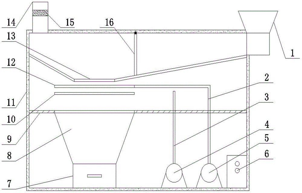
[0022] Such as figure 1 As shown, the present invention comprises the box body 11 that is provided with insulation layer, and described box body 11 side top is equipped with feed hopper 1, and the other side top end of box body 11 is equipped with chimney 14, and described box body 11 interior level Partition plate 9 is set, and partition plate 9 divides casing 11 into two cavities up and down, and the upper cavity is a combustion chamber, and a fire grate 13 for carrying garbage is horizontally provided in the upper cavity, and the opposite ends of the fire grate 13 are provided with There is an upward inclined surface, one inclined surface of the fire grate 13 extends to the inner surface of the box body 11, and the other inclined surface of the fire grate 13 extends to the bottom of the feed hopper 1, and the inner top surface of the box body 11 is close to the feed hopper. 1 A sealing flap 16 is installed between the slopes of the grate 13 on the bottom side, and the sealing


PUM


Abstract

The invention provides a trash burning chamber structure which comprises a box with a heat preservation layer. A feed hopper is mounted at the top end of one side of the box, a chimney is mounted at the top end of the other side of the box, and a separating plate is horizontally arranged in the box and divides the box into an upper cavity and a lower cavity; a fire grate is horizontally arranged in the upper cavity, a combustion supporting device is arranged under the fire grate, a filter net is mounted under the combustion supporting device, an opening corresponding to the filter net is formed in the separation plate under the filter net, an ash collecting hopper is mounted below the opening, and the bottom of the ash collecting hopper is connected with an ash outlet door; an oxygen supply fan is mounted in the lower cavity and connected with one end of an oxygen supply pipeline, and the other end of the oxygen supply pipeline stretches into the upper cavity. The trash burning chamber structure is simple and reasonable, the whole trash burning process is sufficient, and the trash burning chamber structure can be suitable for trash incineration of different scales and is convenient to use and popularize.

Description


Claims


Application Information

Patent Timeline
Owner XIAN ALL SAFE SCI & TECH
Why Eureka
Try Eureka