Secondary burning method and special energy-saving furnace for organic-fuel firepot of two-way air blower

An organic fuel and secondary combustion technology, which is applied to solid heating fuels, household cooking utensils, household stoves/stoves, etc., can solve problems such as unreasonable combustion and blasting positions, too large fuel pusher, and unsuitable combustion methods. , to achieve the effect of sufficient decomposition, stable combustion and long service life

Inactive Publication Date: 2006-08-16
孙吉章
View PDF0 Cites 4 Cited by
  • Summary
  • Abstract
  • Description
  • Claims
  • Application Information

AI Technical Summary

Problems solved by technology

However, in the existing top-down combustion method, the combustion and blast position of the blast are unreasonable, especially the position and mode of the upper blast need to be improved, which is not suitable f

Method used


Image

  • Secondary burning method and special energy-saving furnace for organic-fuel firepot of two-way air blower
  • Secondary burning method and special energy-saving furnace for organic-fuel firepot of two-way air blower
  • Secondary burning method and special energy-saving furnace for organic-fuel firepot of two-way air blower

Examples


Embodiment 1

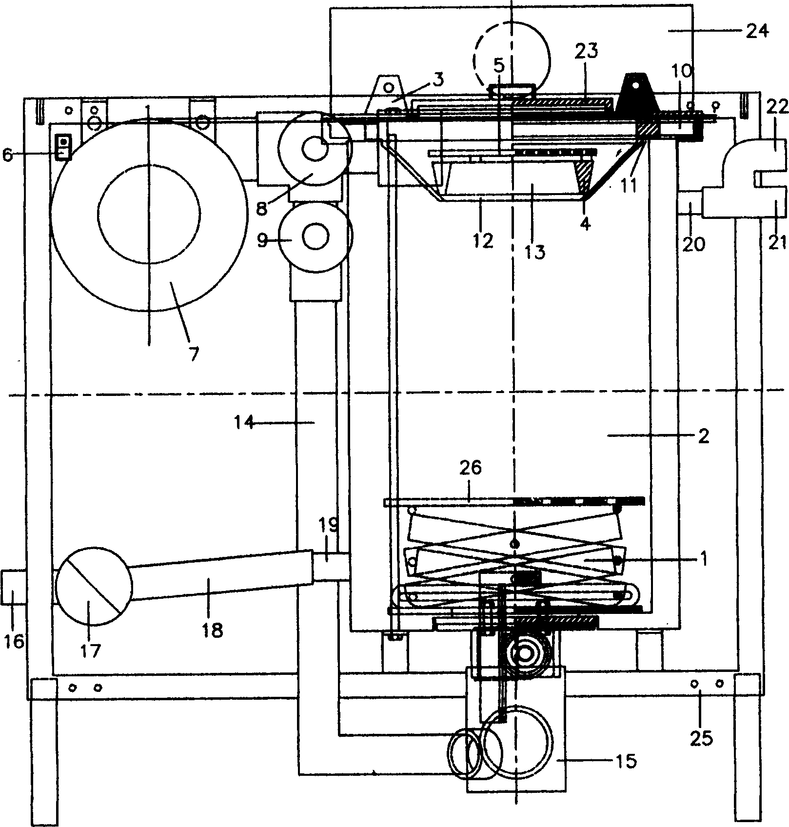
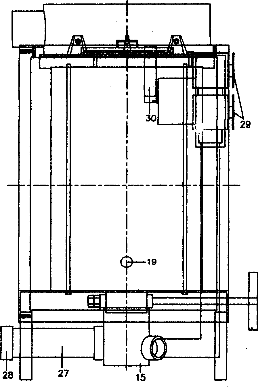
[0024] The secondary combustion method of the two-way blast organic fuel furnace is as follows: the organic fuel is chaff, and a row of firewood can also be placed on the top of the chaff in order to prevent the dust from just being ignited. The firewood is adjusted to just touch the air inlet of the burner head, and the combustion chamber is composed of the fire distribution ring and the fire distribution plate in the burner head above the air inlet of the burner head; the charcoal is filled to 1 / 2 height in the fire distribution ring, and a small piece of charcoal Light it as a fire and put it into the combustion chamber, fill the combustion chamber with charcoal, and cover the fire distribution board; turn on the blower to generate two-way blast, and the blower blows through the annular air inlet channel all the way to add oxygen to the charcoal to make it fully burnt. At the same time, the chaff in the furnace is decomposed to produce hydrocarbon gas; the blower blows air to

Embodiment 2

[0035] Embodiment 2: The furnace body 2 of the special energy-saving furnace is made of refractory material or filled with refractory material between the double-layer furnace body, and the water inlet and outlet devices are omitted. Others are similar to Example 1.


PUM


Abstract

The inventive combustion method consists in: dividing a hearth into a fuel chamber and a combustion chamber; storing the main comburant in the fuel chamber and the secondary combustible material in the combustion chamber and forming annular intake passage in the air intake of the combustion chamber. One way of the blower through the top of the connected stove forms the annular intake passage, and the combustion chamber is formed among the top air intake disposed at the bottom of the top, a fire-separating plate on the fire-separating ring. The other way through the air-vent at the bottom of the connected stove realizes the secondary combustion, and meanwhile joins pushing, ash-removing and ventilating together.

Description


Claims


Application Information

Patent Timeline
Owner 孙吉章
Why Eureka
Try Eureka