Shut-off valve for liquid and gaseous media

A technology of gaseous medium, stop valve, applied in the direction of valve details, valve device, valve operation/release device, etc., to achieve the effect of keeping reaction and switching time, saving weight and simple exchange

Active Publication Date: 2015-07-15
OTTO EGELHOF
View PDF10 Cites 0 Cited by
  • Summary
  • Abstract
  • Description
  • Claims
  • Application Information

AI Technical Summary

Benefits of technology

This new design uses an improved mechanism called a shutter valve (a switch) instead of traditional solenoid operated motors. It consists of two parts - a movable driving component and a control system. When there are no power supply available during operation, they work together like a single unit. They move backward when there're more power than needed. However, if any problem occurs while trying to operate them properly, then another set of components becomes necessary. By incorporating these features into the existing structure of the motor itself, the technical effect of this innovative technology will improve its performance without requiring extra equipment such as batteries.

Problems solved by technology

The technical problem addressed in this patents relates to improving the performance (efficacy) and durability of shut-offs valves used in various industries such as chemicals and power plants. Specifically, existing methods involve increasing costs associated with use of noble metals while sacrificing their ability to work effectively over time. Additionally, conventional techniques involving wires/strips may result in unintended changes in pressure levels within certain parts of the system causing errors even if they were only slightly different types of fuel cells being operated simultanously.

Method used


Image

  • Shut-off valve for liquid and gaseous media
  • Shut-off valve for liquid and gaseous media
  • Shut-off valve for liquid and gaseous media

Examples


Embodiment Construction

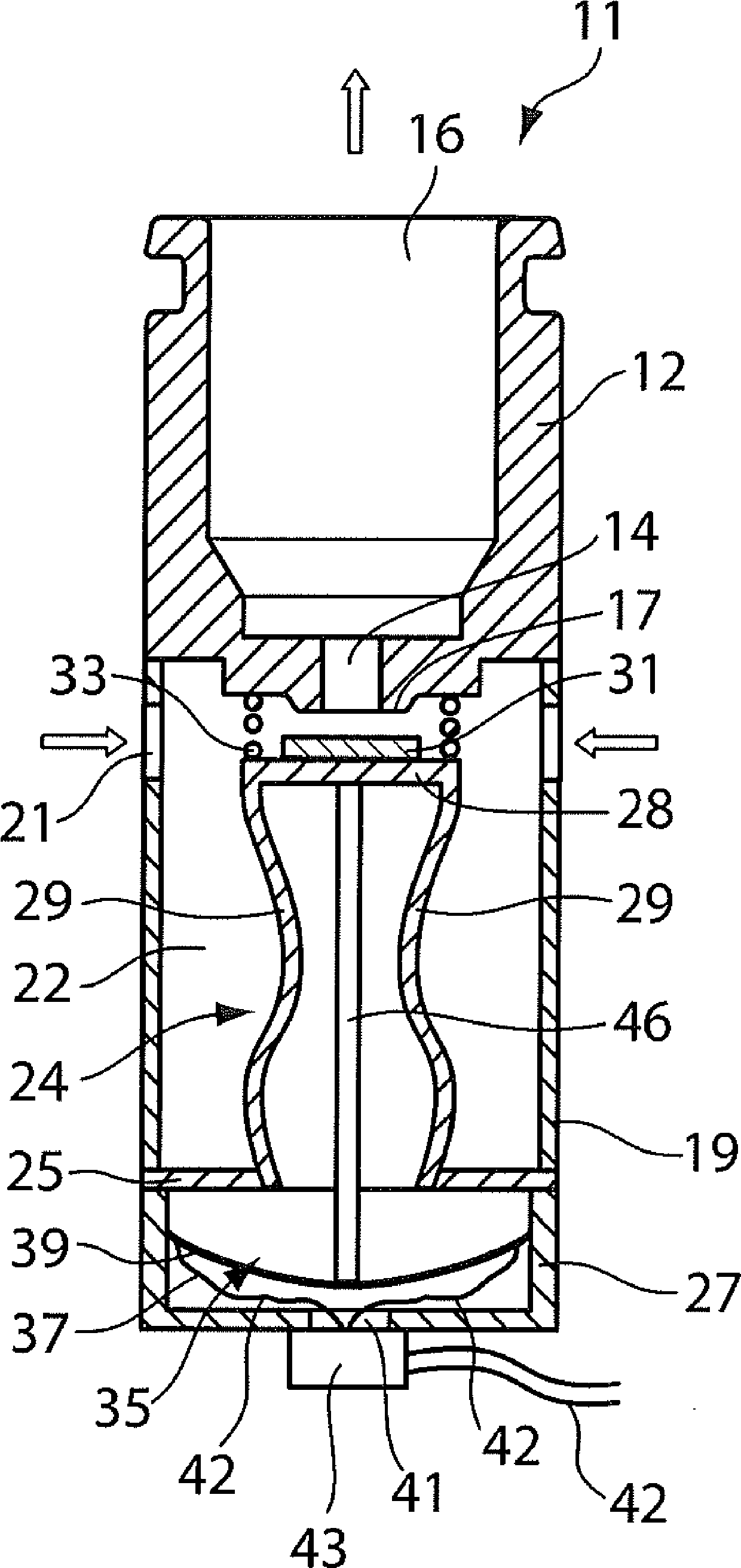
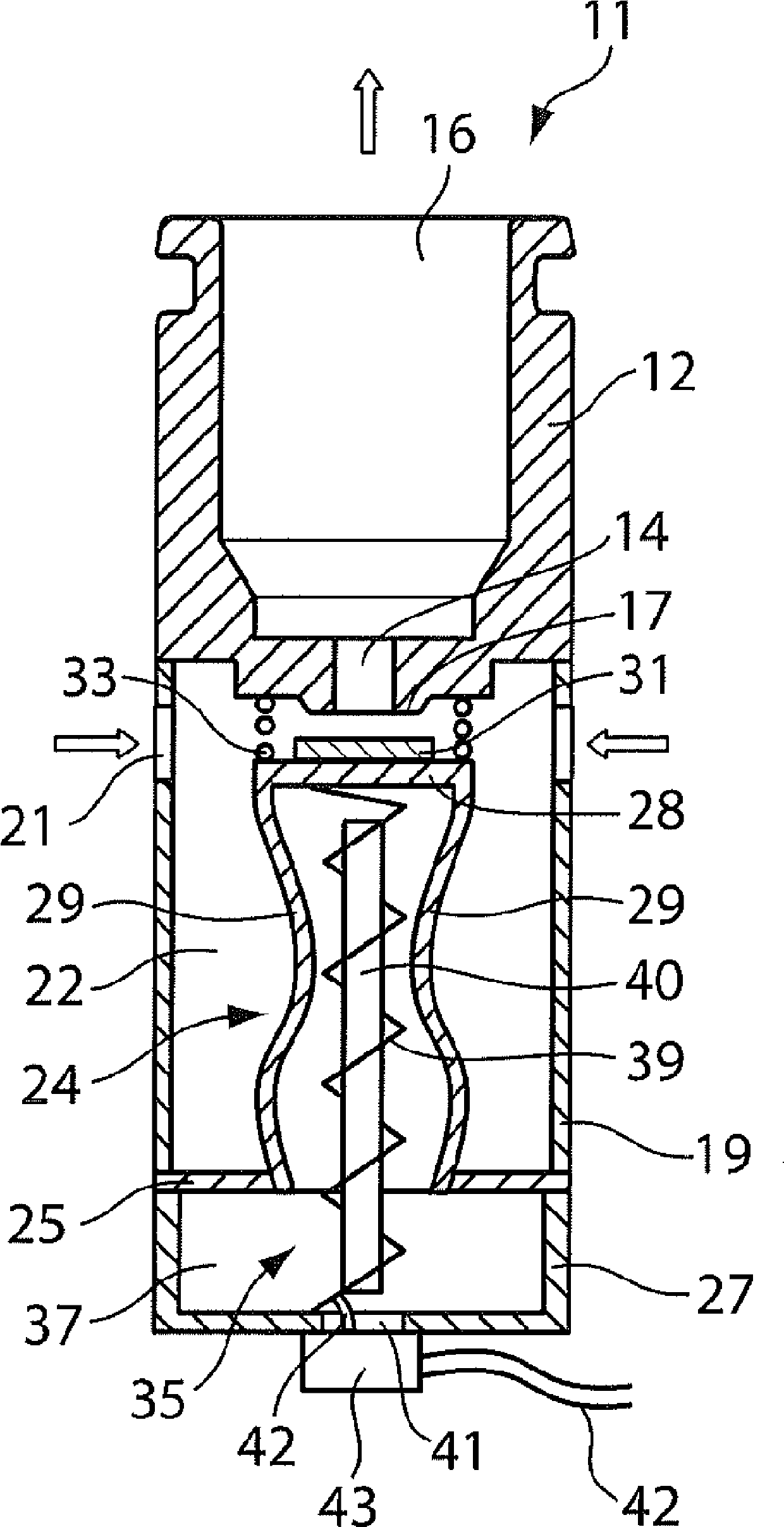
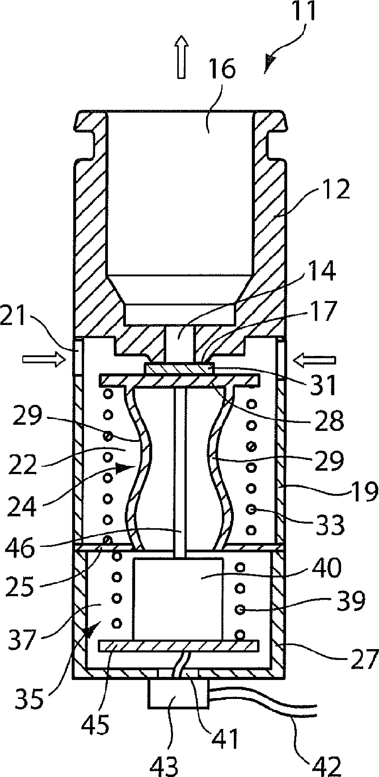
[0028] exist figure 1 A schematic cross-sectional view of a first embodiment of the shut-off valve 11 according to the invention is shown in FIG. The shut-off valve 11 is designed as a so-called NO valve (Normally Open valve), the function of which will be described below.

[0029] The shut-off valve 11 comprises a valve housing 12 which has a passage opening 14 which opens into a discharge opening 16 . A valve seat 17 is arranged on the opposite end of the passage hole 14 , which valve seat may for example be formed as a crater-like protrusion. A sleeve-shaped housing part 19 is also arranged on the valve housing 12 . The housing part 19 may be arranged as a single piece on the valve housing 12 . Alternatively, the housing part 19 can also be attached to the valve housing 12 by a releasable connection (eg a screw connection) or by a firmly glued connection. The sleeve-shaped housing part 19 has at least one inlet opening 21 through which a liquid or gaseous medium is led int


PUM


Abstract

The invention relates to a shut-off valve for liquid or gaseous media, comprising a valve housing (12), which has at least one passage opening (14), which connects an inlet opening (21) to an outlet opening (16), a valve seat (17), which is arranged on the valve housing (12) and surrounds the passage hole (14) and can be closed by a valve closing element (31) lying directly in contact, which are arranged in a control chamber (22) formed in the valve housing (12) between the inlet opening (21) and the outlet opening (16), a drive (35), which can be connected to the valve housing (12) and which actuates the valve closing element (31) in order to open or close the passage hole (14), and a restoring element (33), which acts against a closing or opening motion of the valve closing element (31), wherein the drive (35) has at least one setting element (39) made of a shape-memory alloy in order to actuate the opening or closing motion of the valve closing element (31), and the drive (35) is separated from the control chamber (22) by a sealing element (24).

Description


Claims


Application Information

Patent Timeline
Owner OTTO EGELHOF
Why Eureka
Try Eureka