Power output propeller

A technology of power take-off and power take-off wheel, applied in the direction of transmission, belt/chain/gear, mechanical equipment, etc., can solve problems such as ineffectiveness

Inactive Publication Date: 2015-08-26
熊学智
View PDF8 Cites 0 Cited by
  • Summary
  • Abstract
  • Description
  • Claims
  • Application Information

AI Technical Summary

Problems solved by technology

How to save energy and reduce consumption has become a key research topic for the development of various industries. The main direction is to improve t

Method used


Image

  • Power output propeller
  • Power output propeller

Examples


Embodiment

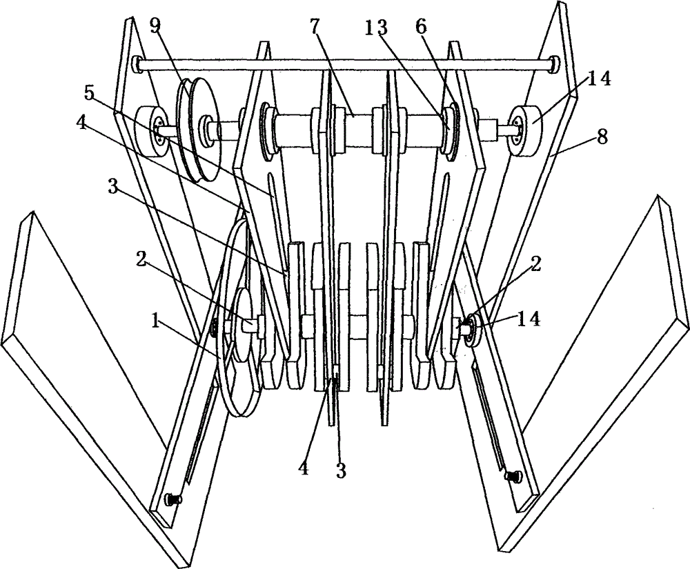
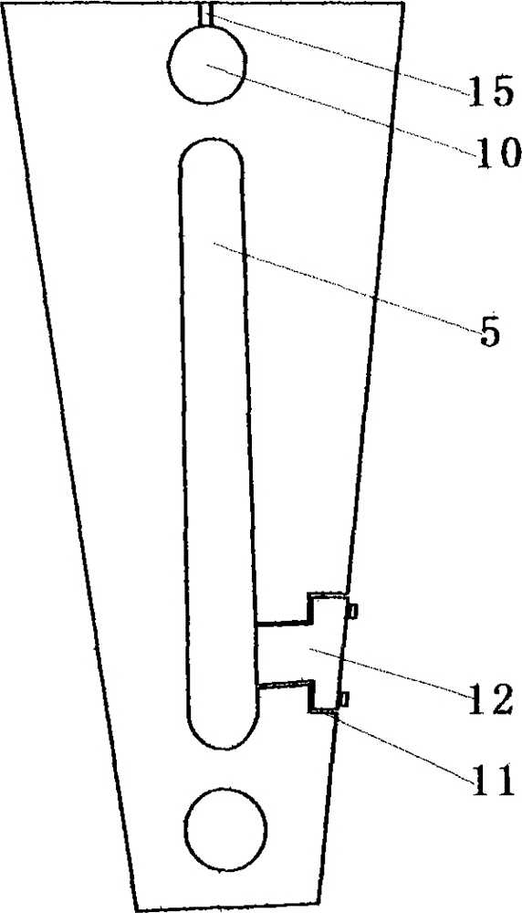
[0013] Example: such as figure 1 As shown, the power output propeller is composed of a power input wheel 1, a crankshaft 2, four connecting rocker arms 4, a one-way shaft 7, a power output wheel 9 and a bracket 8, and the crankshaft 2 and the one-way shaft 7 are fixed on the bracket through bearings 8, the one-way shaft 7 and the crankshaft 2 are in an up-and-down positional relationship, and the top of the connecting rocker arm 4 is provided with a one-way bearing installation hole 10, which is installed on the one-way shaft 7 through the one-way bearing 6, and fastening nuts 13 are used on both sides of the joint Fasten the connection. A chute track 5 is set on the center of the connecting rocker arm 4, which is connected in series with the bellcrank 3 of the crankshaft 2. The bellcrank 3 is located in the chute track 5 and can move along the chute track. The four connecting rocker arms are installed side by side according to this structure to form a linkage overall. The powe


PUM


Abstract

The invention relates to a booster of power output equipment such as an engine, an electric motor and the like, in particular to a power output propeller. The power output propeller comprises a power input wheel, a crankshaft, a plurality of connecting rocker arm, a one-way shaft, a power output wheel and a support, wherein the crankshaft and the one-way shaft are fixed on the support through bearings and are in a vertical position relation; a one-way bearing mounting hole is formed in the top of each connecting rocker arm, and the connecting rocker arms are mounted on the one-way shaft through one-way bearings; a chute track is arranged in the center of each connecting rocker arm and connected in series with one corresponding crank throw of the crankshaft, the crank throws are located in the chute tracks and can move along the chute tracks; the plurality of connecting rocker arms are mounted in parallel according to the structure so as to form the linkage whole. According to the power output propeller, output force of the power equipment such as the engine, the electric motor and the like are further converted and boosted, the power output capacity is increased, and low power input and high power output are realized.

Description


Claims


Application Information

Patent Timeline
Owner 熊学智
Why Eureka
Try Eureka