Lead-acid battery plate with high energy density
A high-energy-density, lead-acid battery technology, applied in lead-acid batteries, battery electrodes, electrode carriers/current collectors, etc. Low efficiency and other problems, to achieve the effect of reducing lead pollution, improving electrical conductivity and corrosion resistance, and low cost
- Summary
- Abstract
- Description
- Claims
- Application Information
AI Technical Summary
Problems solved by technology
Method used
Image

Examples
Example Embodiment
[0025] Example 1
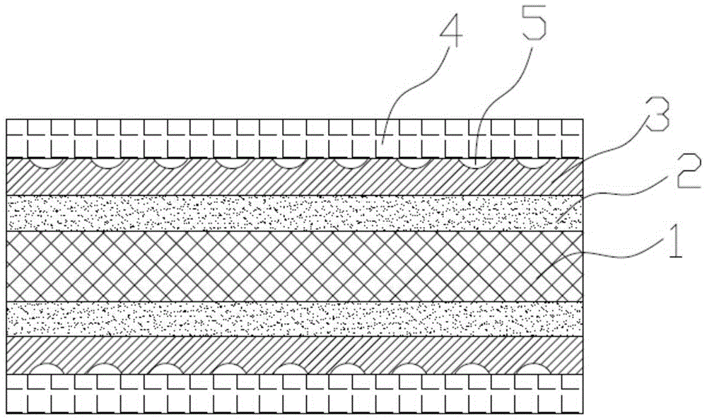
[0026] Such as figure 1 The shown a high energy density lead-acid battery plate includes a composite current collector and a lead paste 4 coated on the surface of the composite current collector. The composite current collector includes a substrate 1, a thickness of 5 μm coated on both sides of the substrate The conductive adhesive transition layer 2 and the conductive anti-corrosion layer 3 with a thickness of 50 μm coated on the surface of the conductive adhesive transition layer. The surface of the conductive anti-corrosion layer is provided with a number of hemispherical pits 5, and the substrate is a metal with a thickness of 0.01 mm Foil, conductive adhesive transition layer is composed of conductive agent A and binder, conductive agent A is activated carbon and activated carbon fiber (mass ratio 1:1); binder is epoxy resin, phenolic resin and acrylic resin (mass ratio 1:1:2), the mass ratio of conductive agent A to binder is 3:1; the conductive anticorrosiv
Example Embodiment
[0029] Example 2
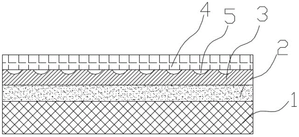
[0030] The difference between this embodiment and embodiment 1 is that the conductive adhesive transition layer 2 is coated on one side of the substrate (see figure 2 ), the rest are exactly the same, so I won’t repeat them here.
Example Embodiment
[0031] Example 3
[0032] The structure of the electrode plate of the high energy density lead-acid battery in this embodiment is the same as that of embodiment 1, except that the thickness of the conductive adhesive transition layer 2 is 10 μm, the thickness of the conductive anticorrosive layer 3 is 100 μm, and the base material is the thickness 1mm perforated mesh, conductive agent A is carbon chopped fiber; the binder is acetic acid-vinyl acetate resin and polyurethane (mass ratio 1:1), the mass ratio of conductive agent A to binder is 4:1; conductive Agent B is carbon nanotube and acetylene black (mass ratio 3:2), the preservative is polypropylene, and the mass ratio of conductive agent B to preservative is 5:1.
[0033] The composite current collector is made by the following method:
[0034] (1) Disperse the conductive agent A, the binder, and the auxiliary agent in an organic solvent to make a slurry with a viscosity of 4000mPa·S, then apply the slurry to both sides of the subs
PUM
| Property | Measurement | Unit |
|---|---|---|
| Thickness | aaaaa | aaaaa |
| Thickness | aaaaa | aaaaa |
| Thickness | aaaaa | aaaaa |
Abstract
Description
Claims
Application Information
 - R&D Engineer
- R&D Manager
- IP Professional
- Industry Leading Data Capabilities
- Powerful AI technology
- Patent DNA Extraction
Browse by: Latest US Patents, China's latest patents, Technical Efficacy Thesaurus, Application Domain, Technology Topic.
© 2024 PatSnap. All rights reserved.Legal|Privacy policy|Modern Slavery Act Transparency Statement|Sitemap